Electrical heater with particular application to humidification and fluid warming

a heater and electric technology, applied in the field of electric heaters, can solve the problems of increasing the size and weight of the device, increasing the risk of leakage between the sealed components, and difficulty in installing the water tub for some users, and achieve the effect of reducing the number of parts and simple assembly process

Active Publication Date: 2010-06-17
RESMED LTD
View PDF12 Cites 63 Cited by
  • Summary
  • Abstract
  • Description
  • Claims
  • Application Information

AI Technical Summary

Benefits of technology

[0016]Another aspect of the invention relates to a method for manufacturing a humidifier comprising an in-mold heater element. In a further aspect the humidifier has a reduced number of parts and / or simple assembly process.

Problems solved by technology

However, such spring loaded heater plates can provide a friction force against insertion of the water tub, which may make installation of the water tub difficult for some users, especially older or frail users.
This results in multiple components that require assembly during manufacture of the humidifier and increase the size and weight of the device.
Furthermore, the assembled construction provides an increased risk of leakage between the sealed components.
Other forms of heaters are known but have rarely, or not at all, been used in commercially available respiratory humidifiers to date.
Conventional humidifiers have the disadvantage of many different components that require assembly and increase weight.
The assembly of different components and the use of heater plates and tubs with conductive base plates provides an increased risk of water leakage.

Method used


Image

  • Electrical heater with particular application to humidification and fluid warming
  • Electrical heater with particular application to humidification and fluid warming
  • Electrical heater with particular application to humidification and fluid warming

Examples


tenth embodiment

Heater Element Tenth Embodiment

[0074]Referring to FIG. 4j, the heater element circuit may be formed of conductive ink(s) 44, and a film or foil 43 may locate, connect, and / or thermally protect a thermal sensor 90, 94, e.g. a thermistor. The thermal sensor may then be overmolded 57 to control the thermal properties of the sensor, and / or to insulate the sensor from the water of a humidifier tub.

eleventh embodiment

Heater Element Eleventh Embodiment

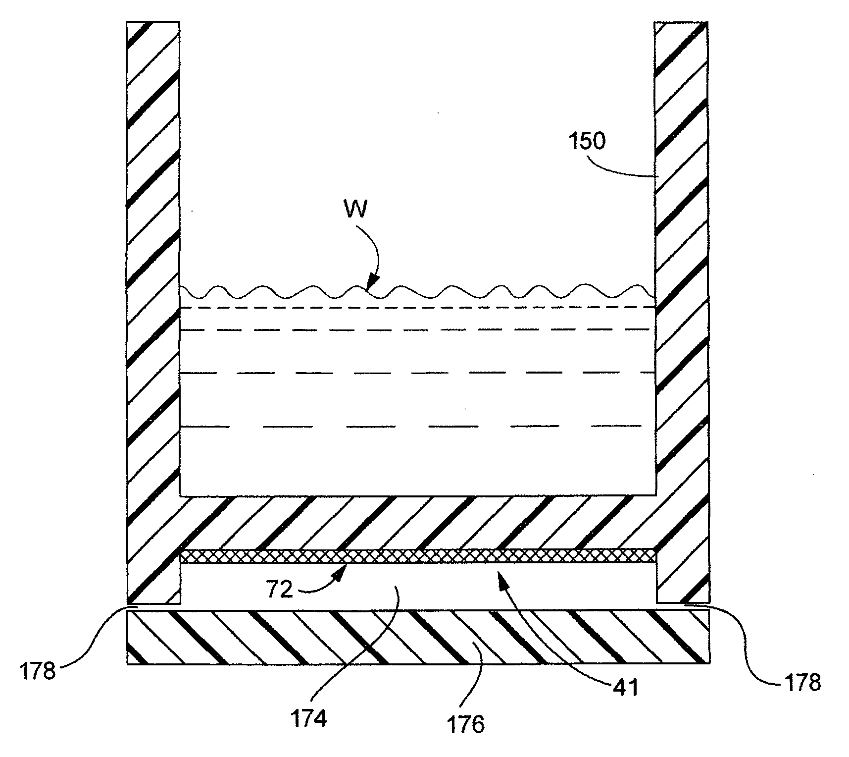
[0075]As shown in FIG. 4k, the heater element may be either a printed film heater element 72, a stamped film heater element 73, and / or an overmolded heater element 75 and may be formed in a shape, for example a spiral, that is configured to cause differential heating to thereby cause water currents to form. For example, the heater element may be configured to create a swirling flow. As another example, the heater element may be formed with portions causing differential heating in areas of a humidifier where water flow may tend to be reduced, or stagnant, compared to other portions of the humidifier.

[0076]In the embodiments discussed above, any suitable molding resin may be used, including such resins as polycarbonate, polycarbonate ABS blends such as Astaloy™, polyethylene and polypropylene. The molded object 46 may be formed using extrusion molding or injection molding techniques or any other appropriate molding techniques. The molded object 46 com...

first embodiment

Control System First Embodiment

[0092]The level of heating by the in-mold heater elements may be controlled using a temperature sensor such as a thermistor or thermocouple. In a sample embodiment shown in FIG. 11, the in-mold heater 72 includes one or more thermistors 90, 92 electrically in series with the power supply and the printed conductive ink 44 on the film 42. Depending upon the application, a positive temperature coefficient (PTC) thermistor or a negative temperature coefficient (NTC) thermistor may be used to control the level of heating. For example, a PTC thermistor operates to decrease the heating power to the heater element as the temperature increases towards the desired temperature. A PTC thermistor may be used in a respiratory humidifier device.


PUM


Abstract

A humidifier includes a tub configured to contain a supply of water and a heater including a first polymer film having an electrically conductive circuit provided upon a surface. The first polymer film is electrically insulating and the tub is formed of molded resin and the heater is molded at least partially within the resin. A respiratory apparatus for delivering a flow of breathable gas to a patient includes the humidifier. A method of humidifying a flow of pressurized breathable gas includes passing the flow of pressurized breathable gas over a supply of water contained in a tub. The tub is formed of molded resin and a heater including a first polymer film having an electrically conductive circuit on a first surface is molded at least partially within the resin.

Description

CROSS REFERENCE TO RELATED APPLICATIONS[0001]This application claims priority to Australian Provisional Applications 2007902992, filed Jun. 5, 2007, and 2007903599, filed Jul. 4, 2007 and U.S. Provisional Application 60 / 986,404, filed Nov. 8, 2007, the entire contents of these applications being incorporated herein by reference in their entirety.FIELD OF THE INVENTION[0002]The present invention relates generally to electrical heaters and particularly to integrated electric heaters for use in heating fluids. More particularly, the present invention relates to in-molded heaters for heating fluids within containers. The electrical heater may be used in a range of devices including, for example, humidification devices, electric jugs, other fluid warming containers, fans and the like. The heater may be used in a respiratory humidification device.BACKGROUND OF THE INVENTION[0003]Respiratory apparatus commonly have devices to alter the humidity of the breathable gas in order to reduce dryi...

Claims


Application Information

Patent Timeline
Patent Type & Authority Applications(United States)
IPC IPC(8): A61M16/16F24F6/00
CPCA61M16/1075G01R19/0092A61M2205/3382A61M2205/3386A61M2205/3389H05B3/46H05B3/48G01F23/241A61M16/109A61M16/162A61M2205/3379A61M2209/02G01F23/22G01F23/24A61M16/16A61M16/161A61M2205/3368
Inventor ROW, NATHAN JOHNHUBY, RONALD JAMESVIRR, ALEXANDER
Owner RESMED LTD
Why Eureka
Try Eureka