Nanowire thermoelectric device

Active Publication Date: 2010-06-17
IND TECH RES INST
View PDF8 Cites 24 Cited by
  • Summary
  • Abstract
  • Description
  • Claims
  • Application Information

AI Technical Summary

Benefits of technology

[0010]According to the above description, the present invention integrates nanowire structures to thermoelectric device, for improving conversion efficiency of the thermoelectric device. Meanwhile, the thermoelectric device of the present invention is made of a semiconductor material and fabric

Problems solved by technology

Therefore, more heat loss and friction loss occur at the surface of the micro-engine.
In addition, conventional thermoelectric block materials have a restricted area to length ratio due to fabrication.
It l

Method used


Image

  • Nanowire thermoelectric device
  • Nanowire thermoelectric device
  • Nanowire thermoelectric device

Examples


Example

[0015]Accompanied drawing of examples will now be made in detail to the present preferred embodiments of the invention. Wherever possible, the same reference numbers are used in the drawings and the description to refer to the same or like parts.

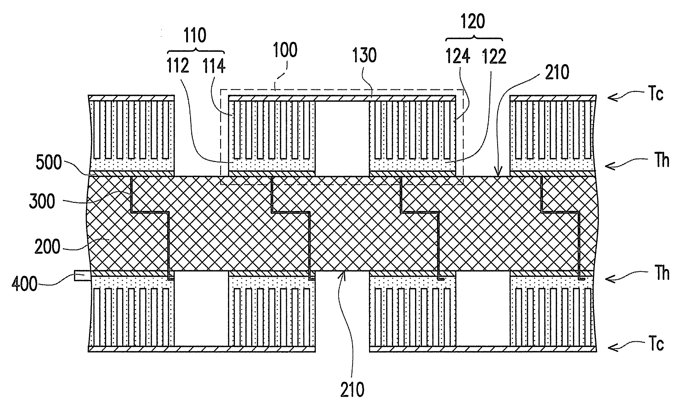
[0016]The present invention provides a thermoelectric device. In accordance with the thermoelectric characteristic, the thermoelectric device converts a thermal energy existed over two ends of a thermoelectric material into an electrical energy for outputting. According to the present invention, the thermoelectric material including a nanowire structure combine with a heat source such as a micro-power system, for recycling a heat loss occurred at a high temperature surface of the heat source. In such a way, the combustion intensity of the heat source can be improved, and the heat loss can be used for generating electrical power.

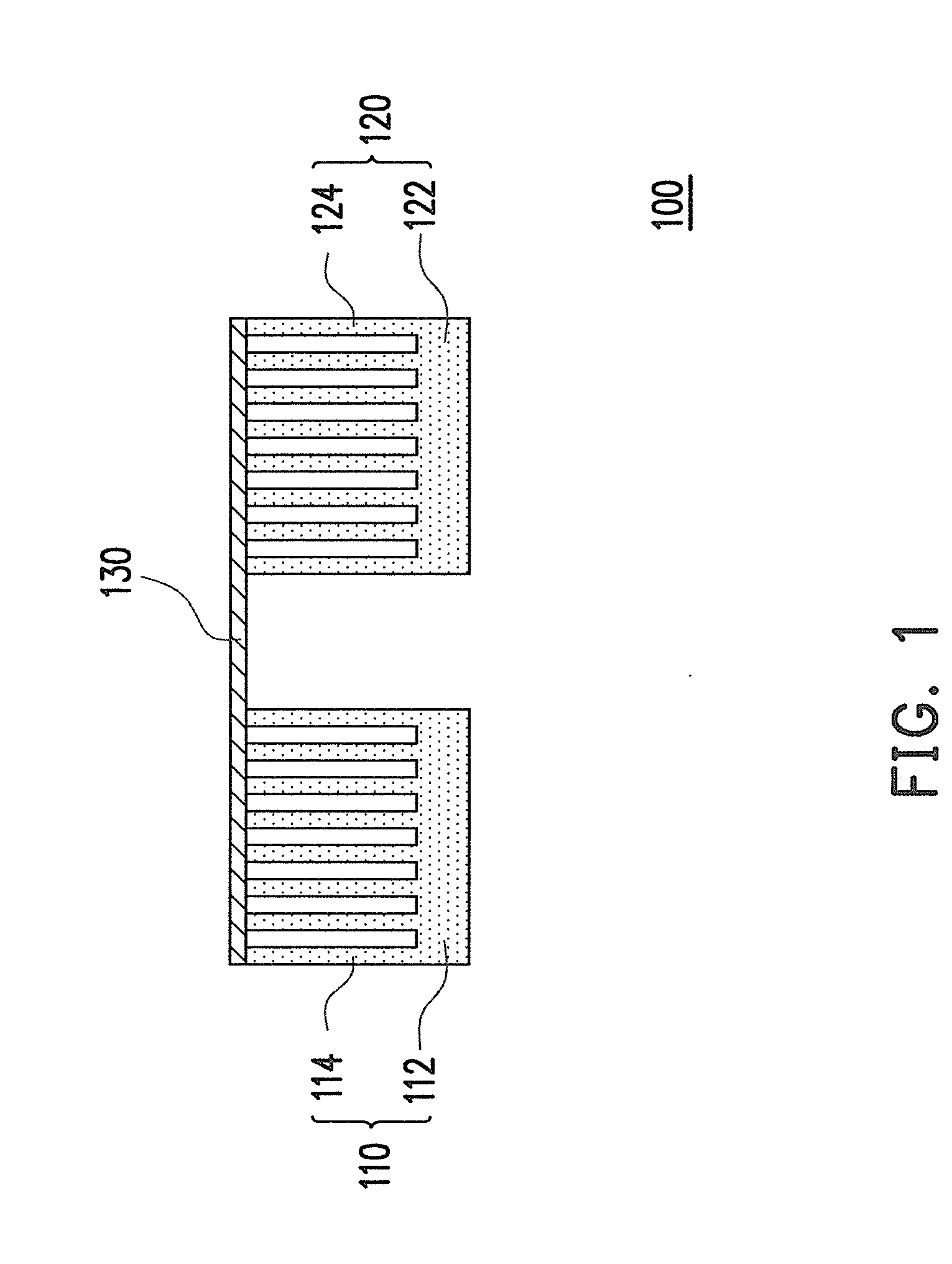
[0017]FIG. 1 is a schematic diagram illustrating a thermoelectric component set according to an embodiment of the p...


PUM


Abstract

A thermoelectric device is provided. The thermoelectric device includes a P-type thermoelectric component, an N-type thermoelectric component, and an electrically conductive layer. Each of the P-type thermoelectric component and the N-type thermoelectric component includes a substrate and a nanowire structure. The conductive layer connects the P-type thermoelectric component set with the N-type thermoelectric component set. The thermoelectric device is adapted for recycling heat generated by the heat source, and for effectively converting the heat into electrical energy.

Description

CROSS-REFERENCE TO RELATED APPLICATION[0001]This application claims the priority benefit of Taiwan application serial no. 97148658, filed on Dec. 12, 2008. The entirety of the above-mentioned patent application is hereby incorporated by reference herein and made a part of this specification.BACKGROUND OF THE INVENTION[0002]1. Field of the Invention[0003]The present invention generally relates to a thermoelectric device, and more particularly, to a thermoelectric device including nanowire structures.[0004]2. Description of Related Art[0005]In accordance with the miniaturizing tendency of electronic and mechanical components or systems, power supplies for driving such systems have also to be correspondingly spatially miniaturized. For example, personal mobile apparatuses, robot systems, and portable systems such as communication devices and electronic products are getting smaller. Correspondingly, the demand for small power supplies is gradually increasing. As such, a power system hav...

Claims


Application Information

Patent Timeline
IPC IPC(8): H01L35/30
CPCH01L35/32H01L35/26H10N10/857H10N10/17
Inventor CHOU, YA-WENJENG, MING-SHANWU, SHIH-KUOYANG, CHANG-CHUNGCHANG, KUEI-CHIEN
Owner IND TECH RES INST
Why Eureka
Try Eureka