High-frequency power apparatus

Active Publication Date: 2007-03-01
DAIHEN CORP
View PDF6 Cites 5 Cited by
  • Summary
  • Abstract
  • Description
  • Claims
  • Application Information

AI Technical Summary

Benefits of technology

[0017] The invention is made in view of the above-mentioned problem, and it is an object of an embodiment of the invention to provide a high-frequency power apparatus capable of performing control such that the value of high-frequency power supplied to a load is equal to an output power set value and of improving the conversion efficiency of an amplifier from DC power to high-fr

Problems solved by technology

However, in this case, the operation should be performed on every high-freque

Method used


Image

  • High-frequency power apparatus
  • High-frequency power apparatus
  • High-frequency power apparatus

Examples


Example

First Embodiment

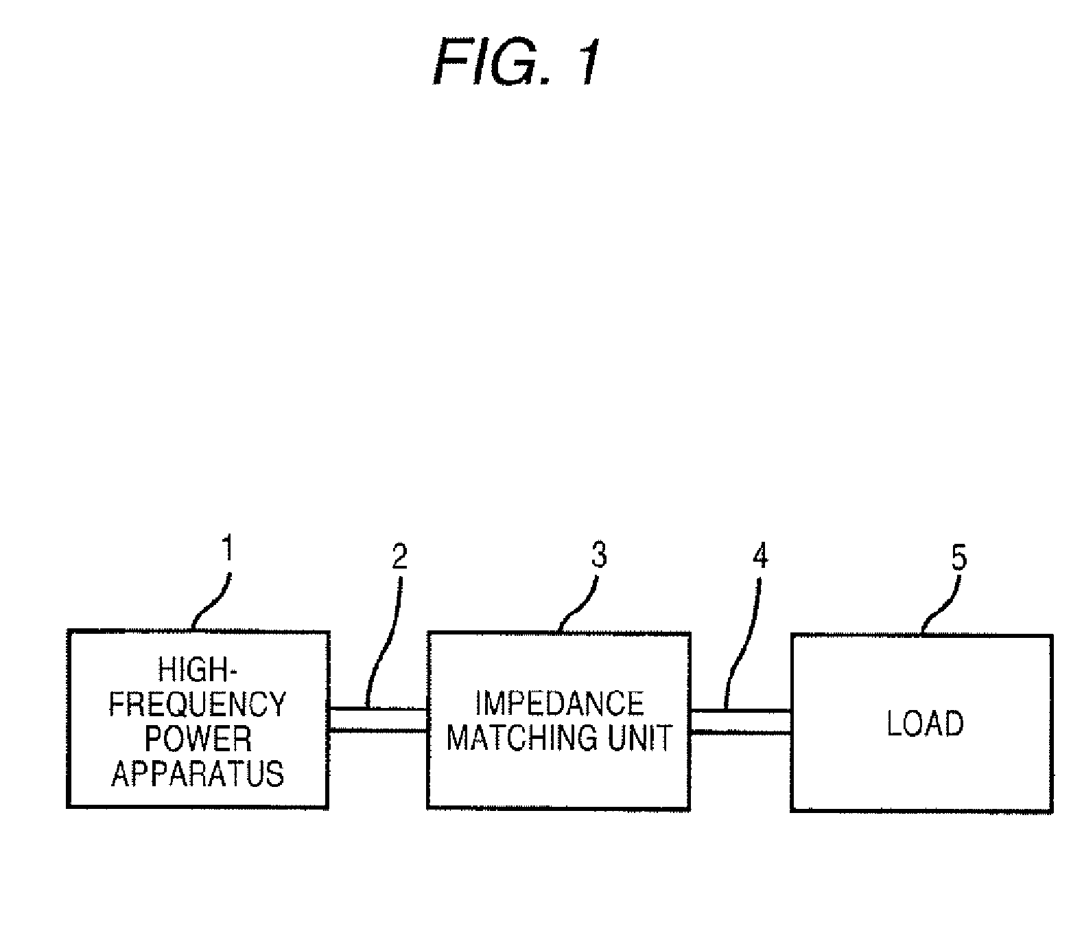
[0055]FIG. 1 is a diagram illustrating an example of a high-frequency power apparatus system having a high-frequency power apparatus according to a first embodiment applied thereto. The high-frequency power apparatus system supplies high-frequency power to an object to be processed, such as a semiconductor wafer or a liquid crystal substrate, to perform processing, such as plasma etching. The high-frequency power apparatus system includes a high-frequency power apparatus 1, transmission lines 2, an impedance matching unit 3, a load connecting unit 4, and a load 5. Alternatively, the high-frequency power apparatus system may not be provided with the impedance matching unit 3.

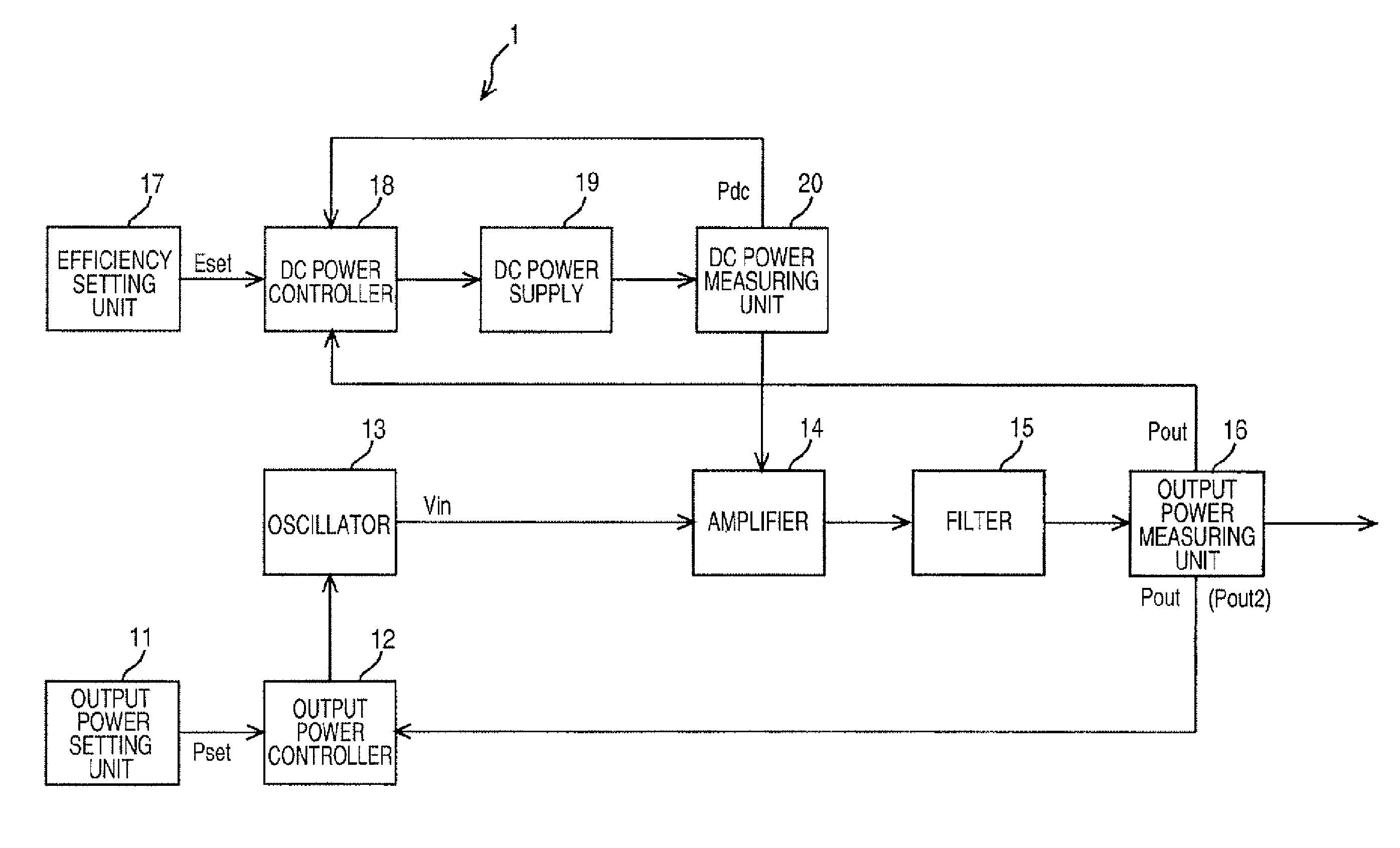
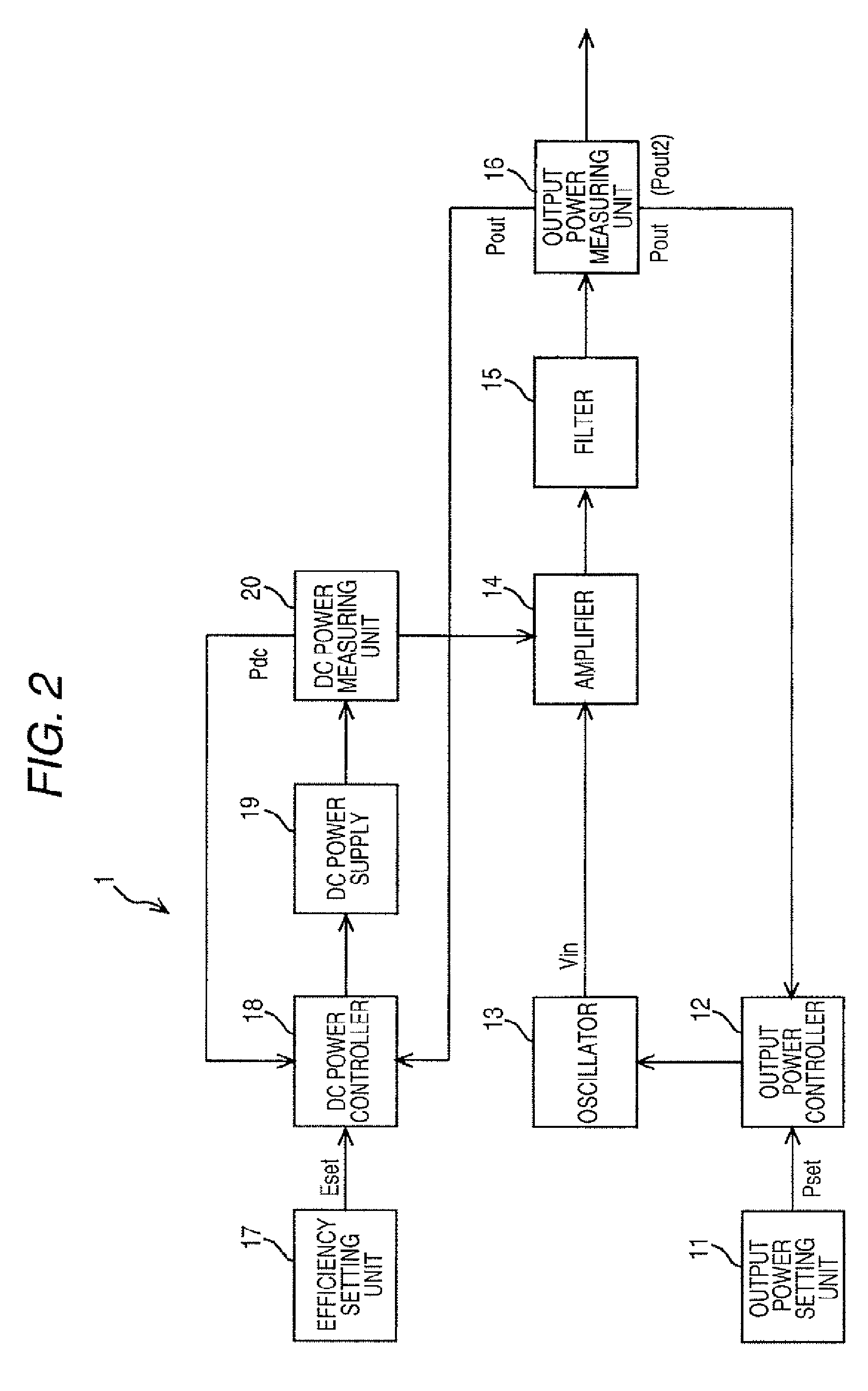
[0056] The high-frequency power apparatus 1 amplifies a high-frequency signal output from an oscillator, which will be described later, by using a power amplifier 14 to output high-frequency power and supplies the high-frequency power to the load 5. In addition, the high-frequency power output f...

Example

Second Embodiment

[0089]FIG. 8 is a block diagram illustrating an example of a high-frequency power apparatus system having a high-frequency power apparatus 1a according to a second embodiment of the invention applied thereto.

[0090] The high-frequency power apparatus system shown in FIG. 8 is similar to the high-frequency power apparatus system shown in FIG. 2 except that the filter is not provided. Therefore, in this embodiment, a description of the same components as those in the first embodiment wilt be omitted.

[0091] As described in the first embodiment, when the conversion efficiency is set to a high level, the output voltage Vdsl of the amplifying element is saturated. In this state, since distortion occurs in the output waveform of the amplifier 14, the filter 15 needs to be used to improve the waveform. However, when the conversion efficiency is set in the range in which the output voltage Vdsl of the amplifying element is not saturated, no distortion occurs in the output ...


PUM


Abstract

A high-frequency power apparatus including: an oscillator, outputting an oscillating signal, an output level of the oscillating signal being variable; an amplifier, amplifying the oscillating signal output from the oscillator and outputting high-frequency power; a DC power supply, supplying DC power to the amplifier, an output level of the DC power being variable; a high-frequency power measuring unit, measuring a power value of the high-frequency power at an output terminal of the high-frequency power apparatus and outputting the measured power value as a high-frequency power measured value; a DC power measuring unit, measuring a power value of the DC power supplied to the amplifier and outputting the measured DC power value as a DC power measured value; a first controller, controlling the output level of the oscillating signal to be output from the oscillator such that the high-frequency power measured value is substantially equal to an output power set value; and a second controller, controlling the output level of the DC power to be supplied from the DC power supply to the amplifier such that a calculated value obtained by dividing the high-frequency power measured value by the DC power measured value is substantially equal to a predetermined efficiency set value.

Description

BACKGROUND OF THE INVENTION [0001] 1. Technical Field of the Invention [0002] The present invention relates to a high-frequency power apparatus for supplying power to a load, such as a plasma processing device that performs, for example, plasma etching and plasma CVD. [0003] 2. Description of the Related Art [0004] For example, a high-frequency power apparatus disclosed in JP-A-2001-197749 has been proposed. FIG. 9 is a block diagram illustrating the structure of a high-frequency power apparatus 50 according to the related art disclosed in JP-A-2001-197749. [0005] The high-frequency power apparatus 50 includes an output power setting unit 51 for setting an output power value of high-frequency power, an oscillator 53 that varies the output level of an oscillating signal on the basis of a controls signal output from an output power controller 52, which will be described later, an amplifier 54 that amplifies the oscillating signal output from the oscillator 53 to output high-frequency ...

Claims


Application Information

Patent Timeline
IPC IPC(8): H02M1/12
CPCH02M7/53806H02M1/42H02M7/48G05F1/12H03F1/02
Inventor KOTANI, HIROYUKITAKEI, HIROTAKA
Owner DAIHEN CORP
Why Eureka
Try Eureka