Eureka AIR delivers breakthrough ideas for toughest innovation challenges, trusted by R&D personnel around the world.

Near to Eye Display System and Appliance

a display system and eye display technology, applied in the field of eye display systems, can solve the problem that the flicker is believed to be unnoticeable to most people above about eighty frames per second, and achieve the effect of compactness, compactness and economics

Inactive Publication Date: 2010-06-17
CHAUM DAVID +2
View PDF27 Cites 1515 Cited by
  • Summary
  • Abstract
  • Description
  • Claims
  • Application Information

AI Technical Summary

Benefits of technology

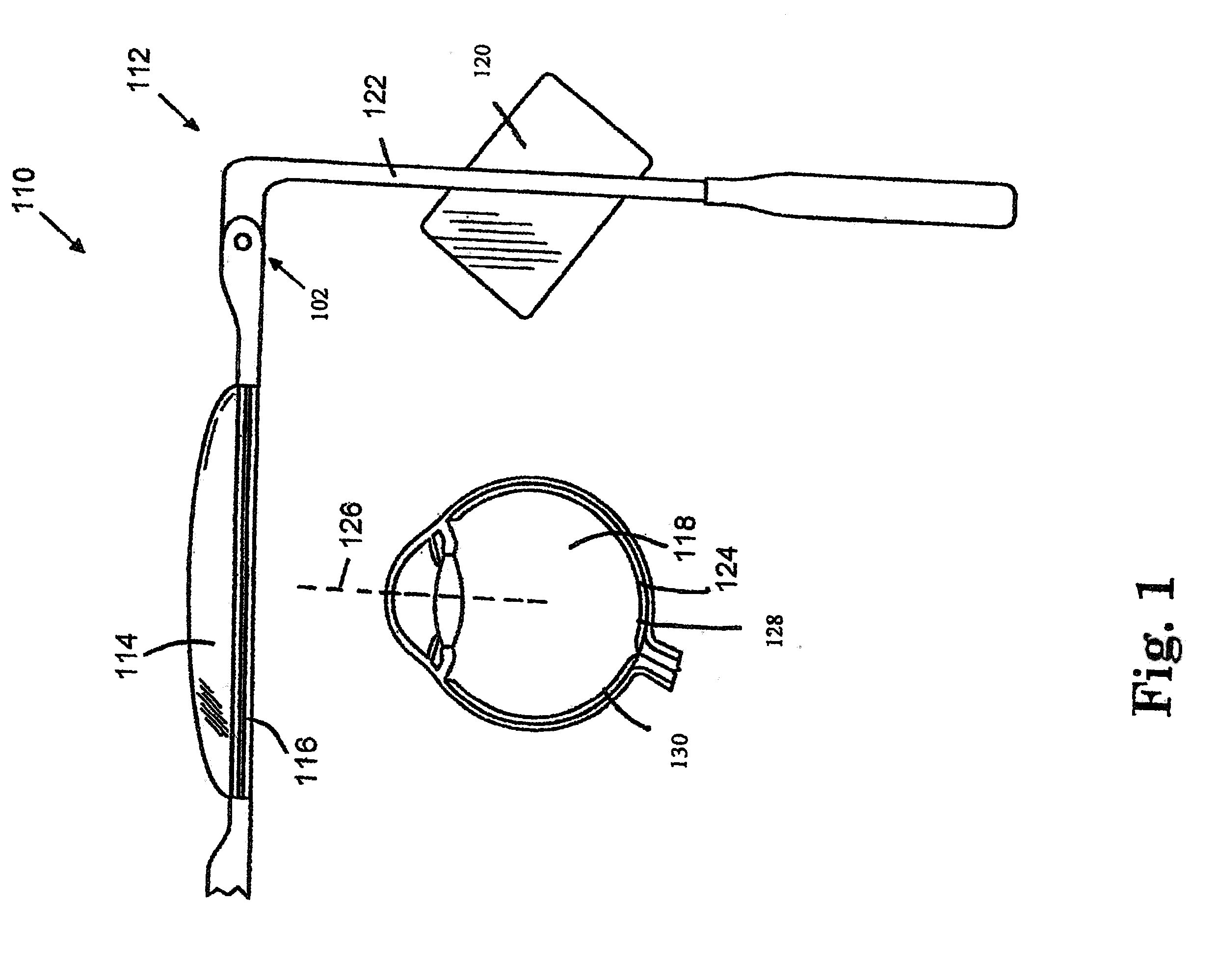
[0014]Recapping, the positioning and orientation of the redirectors and the angles at which light is launched at them may allow them to provide a complete range of angles into the pupil of the eye. Thus, a contiguous image covers a perceived field of view. The foveal portion in some examples receives larger beams from near the point of regard aimed more directly into the eye to provide higher resolution, and the peripheral portion receives optionally smaller beams aimed more obliquely in order to be able to enter the eye pupil.
[0221]201. The method of 195, wherein the stray light reducing structure is switchable and additionally reduces an amount of ambient light that is transmitted through the proximal optic to the eye.

Problems solved by technology

With current display technology, for instance, overall “flicker” is believed to be unnoticeable to most people above about eighty frames per second.

Method used


Image

  • Near to Eye Display System and Appliance
  • Near to Eye Display System and Appliance
  • Near to Eye Display System and Appliance

Examples


example mapping

Procedure

[0707]FIG. 18 shows an example method for mapping a proximal optic and projector system onto a pixel layout (representing, for example, the field of view of a user of the system), where the proximal optic contains two types of redirectors, one to cover the central (foveal) field of view and one to cover the peripheral field of view. In practice, there can be multiple types of redirectors and multiple projector systems for each type. The mapping procedure is believed extensible, provided that the projectors and proximal optic provide full coverage of light to the desired pupil sphere.

[0708]Assume again for clarity that the pixel layout is rectangular, arranged in an X×Y layout with X pixels in the horizontal direction and Y pixels in the vertical direction. Assume further that the projectors are adjustable in two degrees of freedom, namely horizontal and vertical, and that these degrees of freedom can be specified in discrete quantities, say H different horizontal positions ...

example mid

-Level Processing

[0727]The above mapping and scanning procedures provide low-level (within an image frame) examples. FIG. 23 shows an example mid-level (between image frames) processing routine. It starts with the 2300 process next image frame, doing the appropriate processing (as discussed above) to scan the next image frame onto the retina. This step may be repeated some number of times, depending on the refresh rate.

[0728]At this point, certain changes to the user's eye may be checked for. For instance, 2310 has the pupil location changed (as detected by the pupil tracker 1740)? If so, the image displaying may need to be suspended or placed in a holding mode until the new pupil location on the pupil sphere can be predicted or determined (by the pupil tracker 1740), the appropriate image data obtained or reprocessed by the image processor, and new frame data built. In addition, 2320 has the head location changed (as detected by the head tracker 1730). If the head location is being...

example origins

of Light

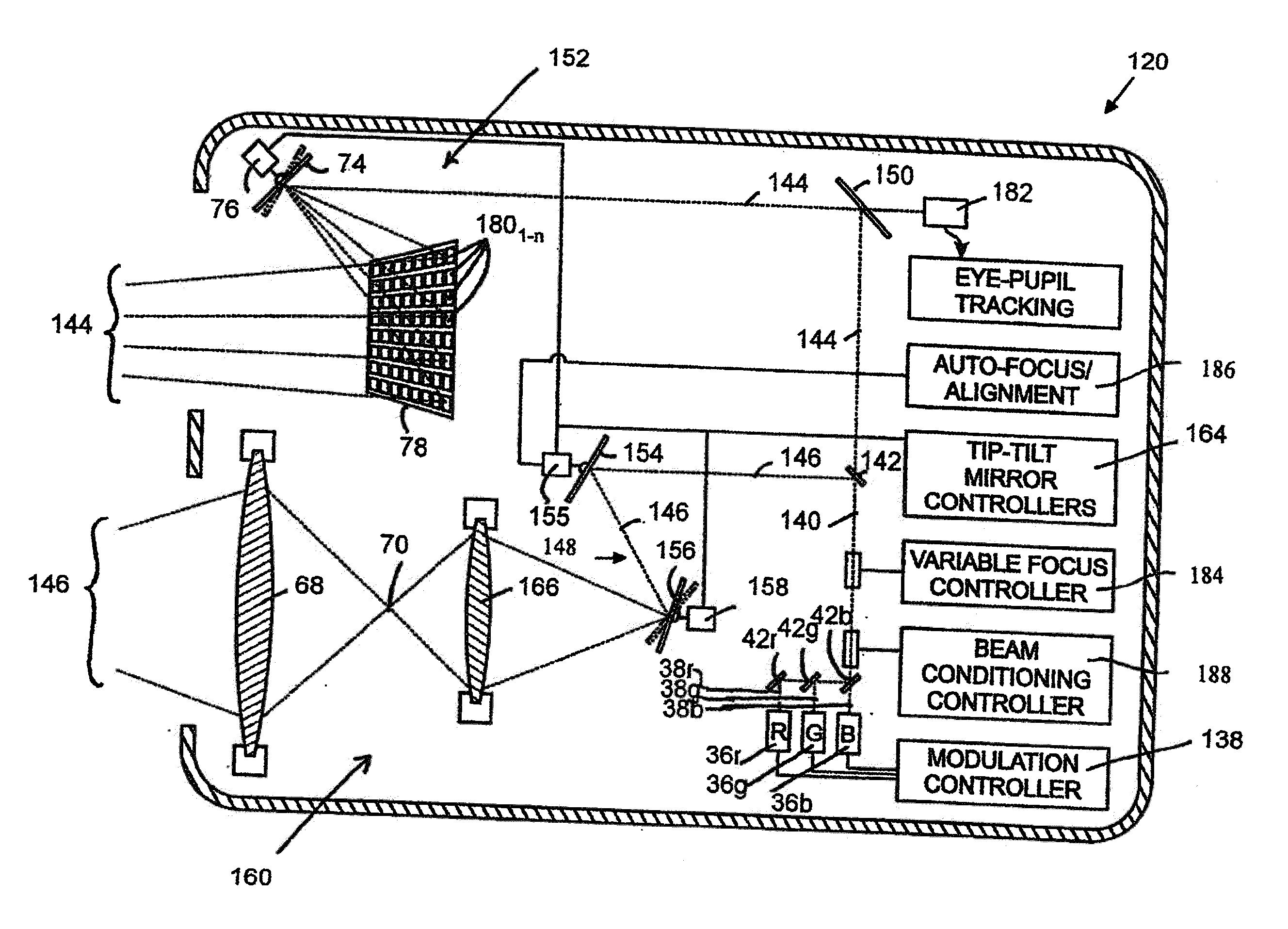
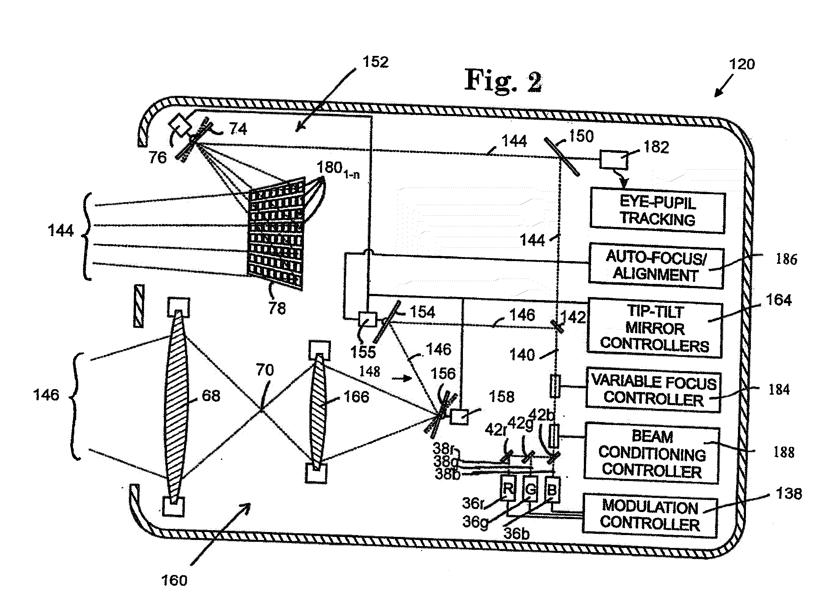
[0791]Turning now to FIG. 34a-d and 35a-d, four exemplary light sourcing configurations are shown. Referring to FIG. 34a, light is modulate and optionally varied in color as it is sourced before being conditioned. The optional combining of beams step in FIG. 34a is shown in FIG. 35d, where a series of beamsplitters serves as an example of a way to combine multiple sources into a collinear beam. It will be understood throughout that if sources are able to deliver a single beam with the desired wavelength or more general spectral density, then combining multiple beams in this way may be obviated; similarly, handling beams of different color separately is also anticipated and as has been mentioned elsewhere here.

[0792]In some examples a source may be split and then each part separately modulated as shown in FIG. 34c; multiple instances of FIG. 35a would provide the structure, one for each split.

[0793]Referring to FIG. 34b, the modulation step is separate from the sourcing and o...


PUM


Abstract

A near-to-eye display system for forming an image as an illuminated region on a retina of at least one eye of a user is disclosed. The system includes a source of modulated light, a proximal optic positionable adjacent an eye of the user to receive the modulated light. The proximal optic has a plurality of groups of optically redirecting regions. The optically redirecting regions are configured to direct a plurality of beams of the modulated light into a pupil of the eye to form a contiguous illuminated portion of the retina of the eye. A first group of the optically redirecting regions is configured to receive modulated light from the source and redirect beams of the modulated light into the pupil of the eye for illumination of a first portion of the retina. A second group of the optically redirecting regions is configured to receive modulated light from the source and redirect beams of the modulated light into the pupil of the eye for illumination of a second portion of the retina.

Description

CROSS-REFERENCE TO RELATED APPLICATION(S)[0001]This application is a continuation in part of PCT Application Nos. PCT / US2009 / 002174, entitled “Proximal Image Projection System,” filed Apr. 6, 2009 and PCT / US2009 / 002182, entitled “Proximal Image Projection System,” filed Apr. 6, 2009, the entire contents of which are incorporated by reference herein. This application claims priority to and the benefit of U.S. Provisional Application Nos. 61 / 042,762, entitled “Proximal-Screen Image Construction,” filed Apr. 6, 2008; 61 / 042,764, entitled “Eyeglasses Enhancements,” filed Apr. 6, 2008; 61 / 042,766, entitled “System for Projecting Images into the Eye,” filed Apr. 6, 2008; 61 / 045,367, entitled “System for Projecting Images into the Eye,” filed Apr. 16, 2008; 61 / 050,189, entitled “Light Sourcing for Image Rendering,” filed May 2, 2008; 61 / 050,602, entitled “Light Sourcing for Image Rendering,” filed May 5, 2008; 61 / 056,056, entitled “Mirror Array Steering and Front-Optic Mirror Arrangements,...

Claims


Application Information

Patent Timeline
Patent Type & Authority Applications(United States)
IPC IPC(8): G09G5/00
CPCG02B27/0093G09G3/2003G09G3/02G02B27/017G02B27/0075G02B27/0172G02B2027/0178
Inventor CHAUM, DAVIDMOSSBERG, THOMAS W.ROGERS, JOHN R.
Owner CHAUM DAVID
Why Eureka
Eureka Blog
Learn More