Measurement method and measurement apparatus

a measurement method and measurement apparatus technology, applied in the direction of mechanical measuring arrangements, instruments, and testing of reflective surfaces, can solve the problems of limited measurement precision of aspheric surfaces, inability to achieve high-precision measurements and processing of aspheric surfaces, and limited euv wavelength range of reflective materials. achieve the effect of high-precision measurements

Inactive Publication Date: 2010-06-17
CANON KK
View PDF12 Cites 16 Cited by
  • Summary
  • Abstract
  • Description
  • Claims
  • Application Information

AI Technical Summary

Benefits of technology

[0015]The present invention provides a measurement method and measurement apparatus capable of performing highly precise measurements of a figure of an aspheric surface as a surface to be tested.

Problems solved by technology

However, reflective materials are also limited for the wavelength range of EUV rays and the reflectivity per single mirror is approximately 70%.
However, with these conventional technologies, there is a limit to the measurement precision for aspheric surfaces (particularly large aperture aspheric surfaces), and highly precise measurements and processing cannot be achieved for aspheric surfaces having an aspheric surface amount above a predetermined value.
As is well known, measurement and processing are inseparable, and it is impossible to carry out precise processing without highly precise measurements.
For example, in the specification of U.S. Pat. No. 6,781,700, depending on the aspheric surface, there are cases where the drive amount v in the optical axis direction exceeds 100 mm, and it is extremely difficult to perform highly precise measurements of such a large drive amount v. Furthermore, when obtaining a position h on the surface to be tested from the drive amount v, it is assumed that all the points in a zone indicate information from positions at which lengths from the optical axis of the surface to be tested are equivalent (hereinafter referred to as equivalent radial positions).
However, in a case where there is error in the spherical waves that illuminate the surface to be tested, or a case where there is distortion or the like in the optical system of the interferometer, the regions where the interference patterns become null are not necessarily limited to those according to reflected light from the equivalent radial positions on the aspheric surface, and therefore error is produced in measurements of positions on the surface to be tested.

Method used


Image

  • Measurement method and measurement apparatus
  • Measurement method and measurement apparatus
  • Measurement method and measurement apparatus

Examples


Embodiment Construction

[0030]Various embodiments of the present invention will be described below with reference to the accompanying drawings. Note that the same reference numerals denote the same members throughout the drawings, and a repetitive description thereof will not be given.

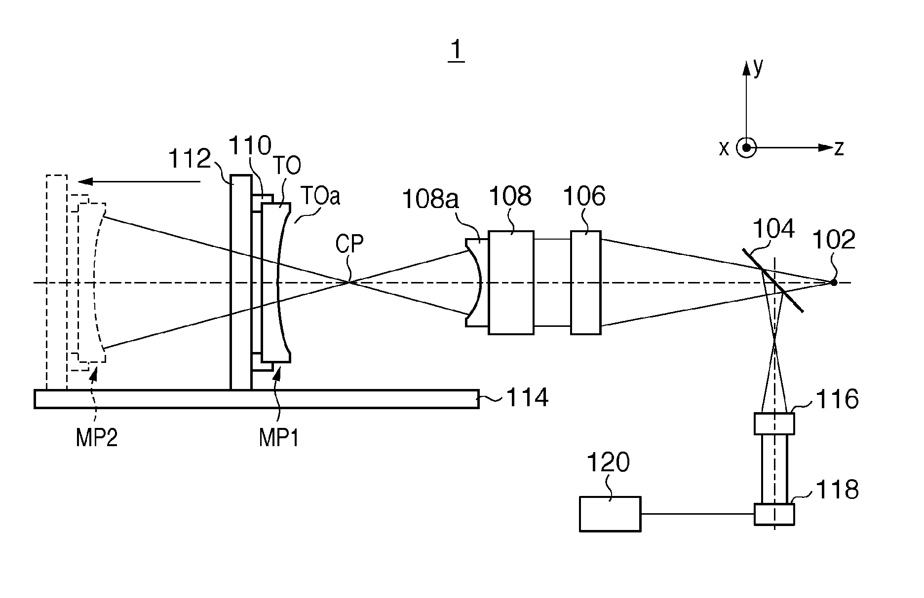
[0031]FIG. 1 is a schematic diagram showing a configuration of a measurement apparatus 1 as one aspect of the present invention. The measurement apparatus 1 is a measurement apparatus that measures a figure of a surface to be tested by illuminating the surface to be tested, which has an aspheric surface, using light beams that form spherical waves that have passed through a reference surface, and in the present embodiment is realized as a Fizeau interferometer.

[0032]As shown in FIG. 1, the measurement apparatus 1 is provided with a light source 102, a half mirror 104, a converging lens 106, a TS lens 108, a reference surface 108a arranged on the TS lens 108, and a holder 110 that holds a test object TO having an aspheric surf...


PUM


Abstract

The present invention provides a measurement apparatus that illuminates a surface to be tested having an aspheric surface using light beams that form spherical waves to measure a figure of the surface to be tested, including a detection unit configured to detect interference patterns between light beams from the surface to be tested and light beams from a reference surface, and a controller configured to control processing for obtaining a figure of the surface to be tested based on the interference patterns detected by the detection unit.

Description

BACKGROUND OF THE INVENTION[0001]1. Field of the Invention[0002]The present invention relates to measurement methods and measurement apparatuses.[0003]2. Description of the Related Art[0004]Innovations in optical systems are brought about by introducing new optical elements or degrees of freedom. For example, improving (enhancing) optical performance by introducing aspheric surfaces is one item that has long been pursued. In recent years, along with advancements in processing technologies and measurement technologies, aspheric surfaces have started to be introduced into exposure apparatuses for semiconductor device manufacturing, which demands the greatest precision. Broadly divided there have been three effects of introducing aspheric surfaces into exposure apparatuses.[0005]A first effect is a reduction in the number of optical elements. In recent years there has been increasing use of short wavelengths in an exposure light and it has been necessary to use high cost glass material...

Claims


Application Information

Patent Timeline
Patent Type & Authority Applications(United States)
IPC IPC(8): G01B11/24G06F15/00
CPCG01B11/2441G01M11/005G01B9/02072G01B9/02057G01B9/02039
Inventor NAKAUCHI, AKIHIRO
Owner CANON KK
Why Eureka
Try Eureka