Aquifer replenishment system with filter

a replenishment system and filter technology, applied in the field of concrete structures, can solve the problems of not giving much consideration to replenishment, depleting supply, and supply not being renewed as quickly, and achieve the effect of increasing porosity

Active Publication Date: 2010-06-17
OCEANSAFE
View PDF36 Cites 21 Cited by
  • Summary
  • Abstract
  • Description
  • Claims
  • Application Information

AI Technical Summary

Benefits of technology

[0014]The aquifer replenishment pavement may include leach lines having a higher porosity than the surrounding leach field. The surface drains may be in direct fluid communication with the leach lines, and the leach lines may be in direct fluid communication with the aggregate drains.
[0015]An aquifer replenishing concrete paving method is also provided, comprising the steps of: (a) clearing and removing the top soil layer until reaching the clay layer; (b) forming an aggregate drain through the clay layer to the sand lens; (c) disposing a first filter within the aggregate drain, the first filter being configured to remove foreign particles from fluid passing therethrough; (d) forming an aggregate leach field above the clay layer; (e) forming a pavement layer above the aggregate leach field; (f) forming a surface drain extending through the concrete layer; and (g) disposing a second filter within the surface drain, the second filter being configured to remove foreign particles from fluid passing therethrough. Additionally, the step of forming the aggregate leach field may also includes the step of forming one or more leach lines therein.

Problems solved by technology

While groundwater extraction methods are well known, much consideration has not been given to the replenishment thereof.
It is not surprising that many aquifers are being overexploited, significantly depleting the supply.
However, in arid and semi-arid regions, the supply cannot be renewed as rapidly as it is being withdrawn because the natural process takes years, even centuries, to complete.
When aquifers are depressurized or depleted, the overall capacity is decreased, and subsidence may occur.
It is well recognized that such low-lying and subsided areas have many attendant public safety and welfare problems, particularly when flooding or other like natural disasters occur.
The problem of rapid depletion is particularly compounded in developed areas such as cities and towns, where roads, buildings, and other man-made structures block the natural absorption of precipitation through permeable soil.
In fact, porous material would be unsuitable for construction of buildings, where internal moisture is desirably kept to a minimum.
However, the use of such replenishment systems required frequent human intervention.
Additionally, the volume of water that was able to be carried to these re-charging locations was limited, thus limiting the replenishment capacity.
This form of concrete, while allowing limited amounts of water to pass through, was unsuitable for paving purposes because of its reduced strength.
Additionally, the aforementioned drainage systems were still required because the porous concrete was unable to handle all of the water in a typical rainfall.
Nevertheless, the strength of the structure was insufficient because of the reduced internal bonding force of the concrete due to the lack of an aggregate.
Furthermore, in some instances, surface fluids may include large amounts of foreign particles and / or pollutants.
In this regard, the foreign particles or pollutants may be highly concentrated such that the earth's natural filtration may not be able to sufficiently remove the particles or pollutants before the fluid reaches the aquifer.
If the particles or pollutants are not removed from the fluid, the fluid may contaminate the aquifer.

Method used


Image

  • Aquifer replenishment system with filter
  • Aquifer replenishment system with filter
  • Aquifer replenishment system with filter

Examples


first embodiment

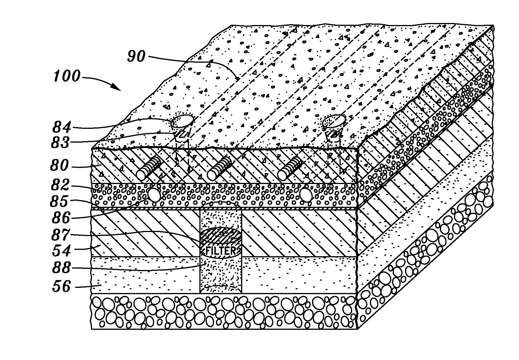
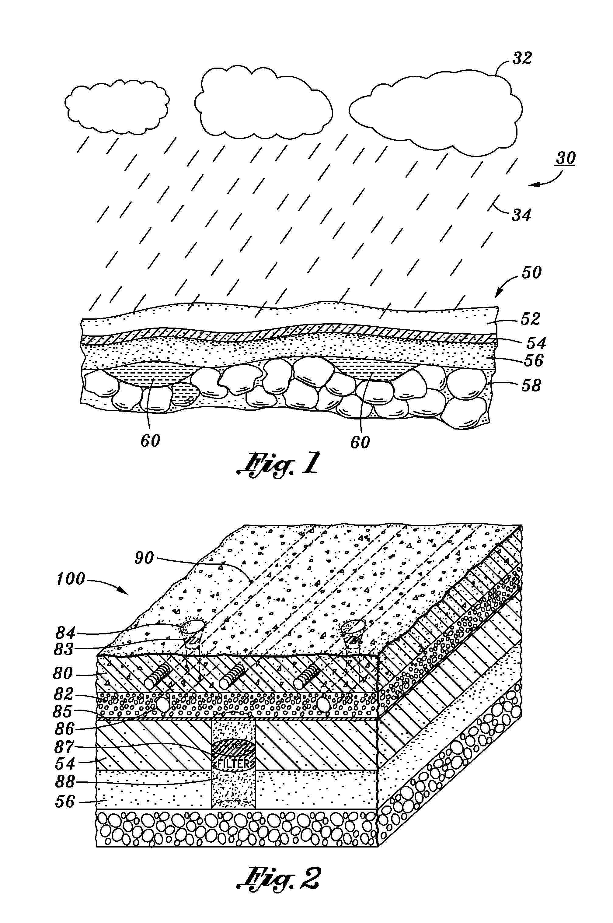
[0028]Referring now to FIG. 2, the present inventive concrete paving system 100 is shown. Situated above clay layer 54 is an aggregate leach field 82 comprised of sand and gravel particles. One embodiment may additionally include a fabric liner 85 disposed between the clay layer 54 and the aggregate leach field 82. The fabric liner 85 may provide soil stabilization as well as enhance the filtration.

[0029]Above aggregate leach field 82 is a pavement layer 80, which by way of example only and not of limitation, is concrete composed of Portland cement and an aggregate. Pavement layer 80 may be reinforced with any reinforcement structures known in the art such as rebar, rods and so forth for increased strength. Preferably, the reinforcement structure has the same coefficient of thermal expansion as the pavement material, for example, steel, where concrete is utilized, to prevent internal stresses in increased temperature environments. By way of example only and not of limitation, paveme...

second embodiment

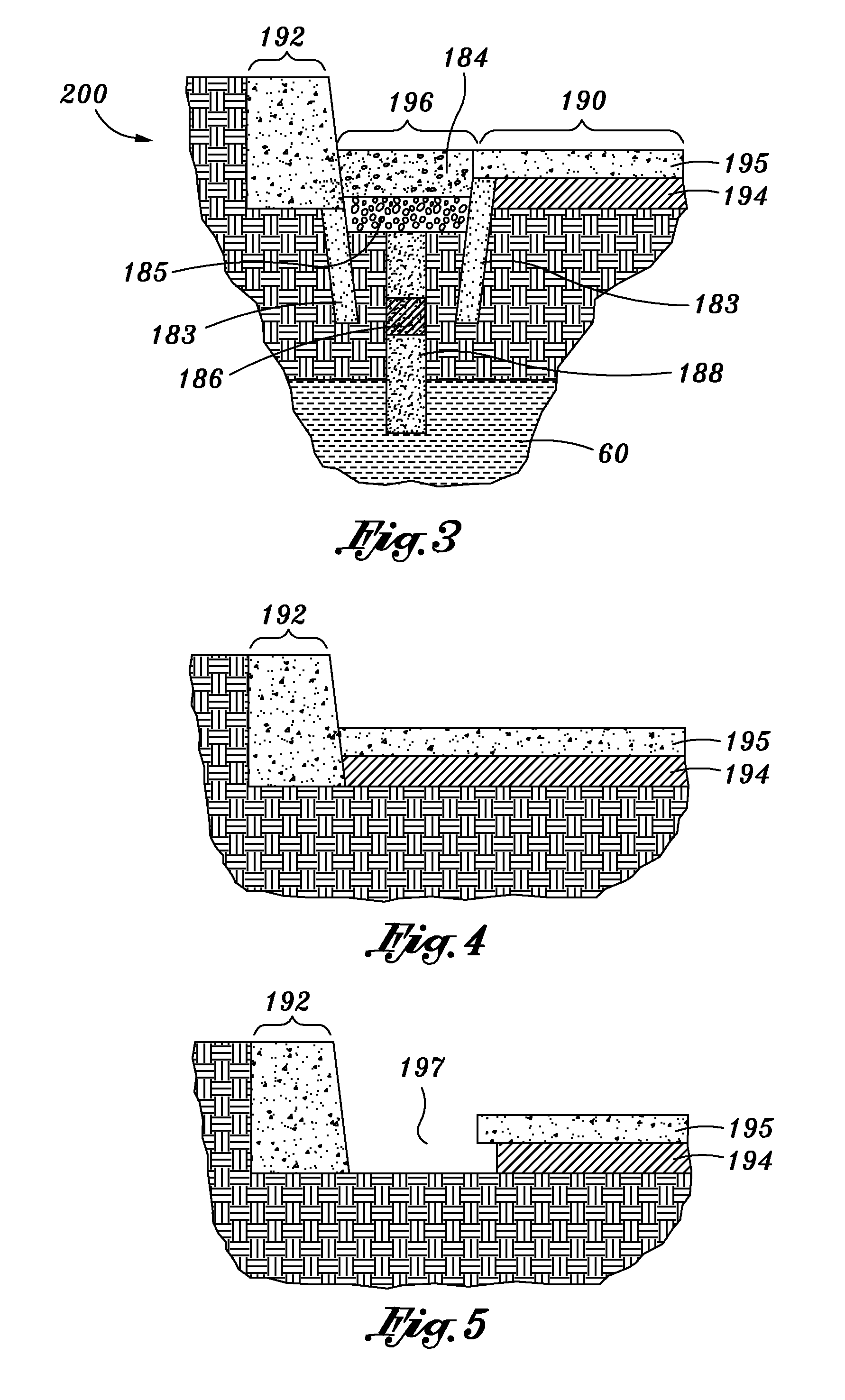
[0040]With reference to FIG. 3, the aquifer replenishing system 200 is shown, including an elevated curb section 192, a gutter section 196, and a road pavement section 190. Road pavement section 190 is comprised of a pavement surface 195, which by way of example only and not of limitation, is architectural concrete, asphalt concrete, or any other paving material known in the art, and is supported by base course 194. Base course 194 is generally comprised of larger grade aggregate, which is spread and compacted to provide a stable base. The aggregate used is typically ¾ inches in size, but can vary between ¾ inches and dust-size.

[0041]In accordance with the present invention, gutter section 196 has a porous concrete gutter 184 in which the top surface thereof is in a substantially co-planar relationship with the top surface of pavement surface 195. Optionally, porous concrete gutter 184 is supported by base 185 which is composed of similar aggregate material as base course 194. Furth...


PUM

PropertyMeasurementUnit
porosityaaaaaaaaaa
permeableaaaaaaaaaa
permeabilityaaaaaaaaaa

Abstract

Provided is an aquifer replenishing pavement formed above soil having a sand lens above the aquifer and a clay layer above the sand lens. The pavement includes an aggregate leach field having an aggregate top surface, and an aggregate bottom surface abutting the clay layer. The pavement further includes a pavement layer having an exposed pavement top surface, and a pavement bottom surface abutting the aggregate leach field. A surface drain extends through the pavement layer to drain fluid from the exposed pavement top surface to the aggregate leach field. An aggregate drain extends from the aggregate leach field into the sand lens through the clay layer to drain fluid from the aggregate leach field into the aquifer. A filter is disposed within one of the surface drain and the aggregate drain. The filter is configured to remove foreign particulates from fluid passing therethrough.

Description

CROSS-REFERENCE TO RELATED APPLICATIONS[0001]This is a continuation-in-part application of application Ser. No. 12 / 011,710, filed Jan. 29, 2008, which is a divisional patent application of application Ser. No. 11 / 489,006, filed Jul. 16, 2006. This is also a continuation-in-part application of application Ser. No. 12 / 417,060, filed Apr. 2, 2009, which is a continuation application of application Ser. No. 12 / 011,682, filed Jan. 29, 2008, which is a divisional patent application of application Ser. No. 11 / 489,006, filed Jul. 16, 2006. This is also a continuation-in-part application of application Ser. No. 12 / 417,064, filed Apr. 2, 2009, which is a continuation application of application Ser. No. 12 / 075,340, filed Mar. 11, 2008, which is a divisional patent application of application Ser. No. 11 / 489,006.STATEMENT RE: FEDERALLY SPONSORED RESEARCH / DEVELOPMENT[0002]Not ApplicableBACKGROUND[0003]1. Technical Field[0004]The present invention generally relates to concrete structures and the m...

Claims


Application Information

Patent Timeline
Patent Type & Authority Applications(United States)
IPC IPC(8): E02B11/00E01C3/06E01C11/22
CPCE01C11/226E01C11/18
Inventor SHAW, RONALDSHAW, LEE A.
Owner OCEANSAFE
Why Eureka
Try Eureka