

Method of manufacturing nano-structure and method of manufacturing a pattern using the method
a nano-structure and pattern technology, applied in the field of manufacturing nano-structures and patterns using the method, can solve the problem that the above-mentioned conventional methods barely form a uniform nano-structure on a large-sized substrate, and achieve the effect of improving the productivity and manufacturing reliability of nano-structures and polarization plates
- Summary
- Abstract
- Description
- Claims
- Application Information
AI Technical Summary
Benefits of technology
Problems solved by technology
Method used
Image

Examples
embodiment 1
Nano-Structure
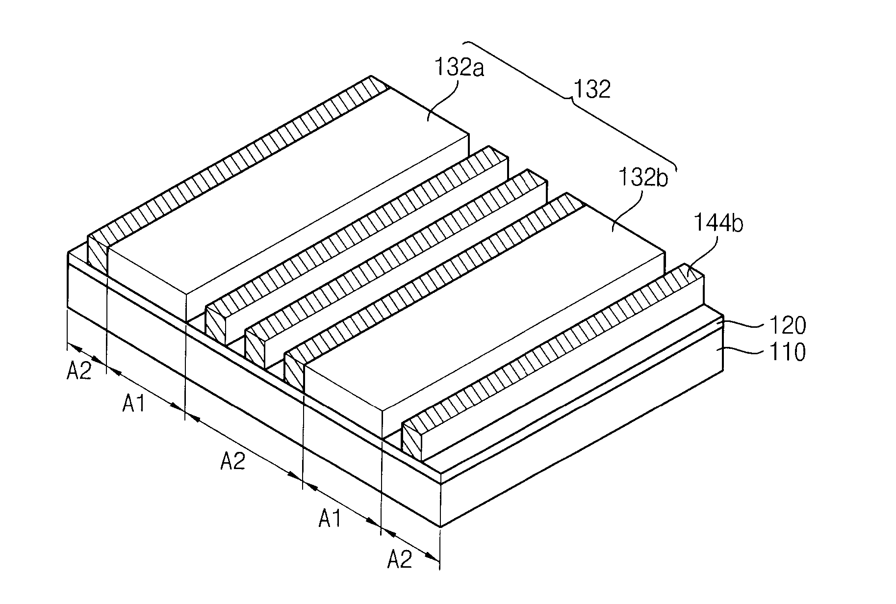
[0070]FIG. 2 is a perspective view illustrating a nano-structure manufactured according to an example embodiment of the present invention.
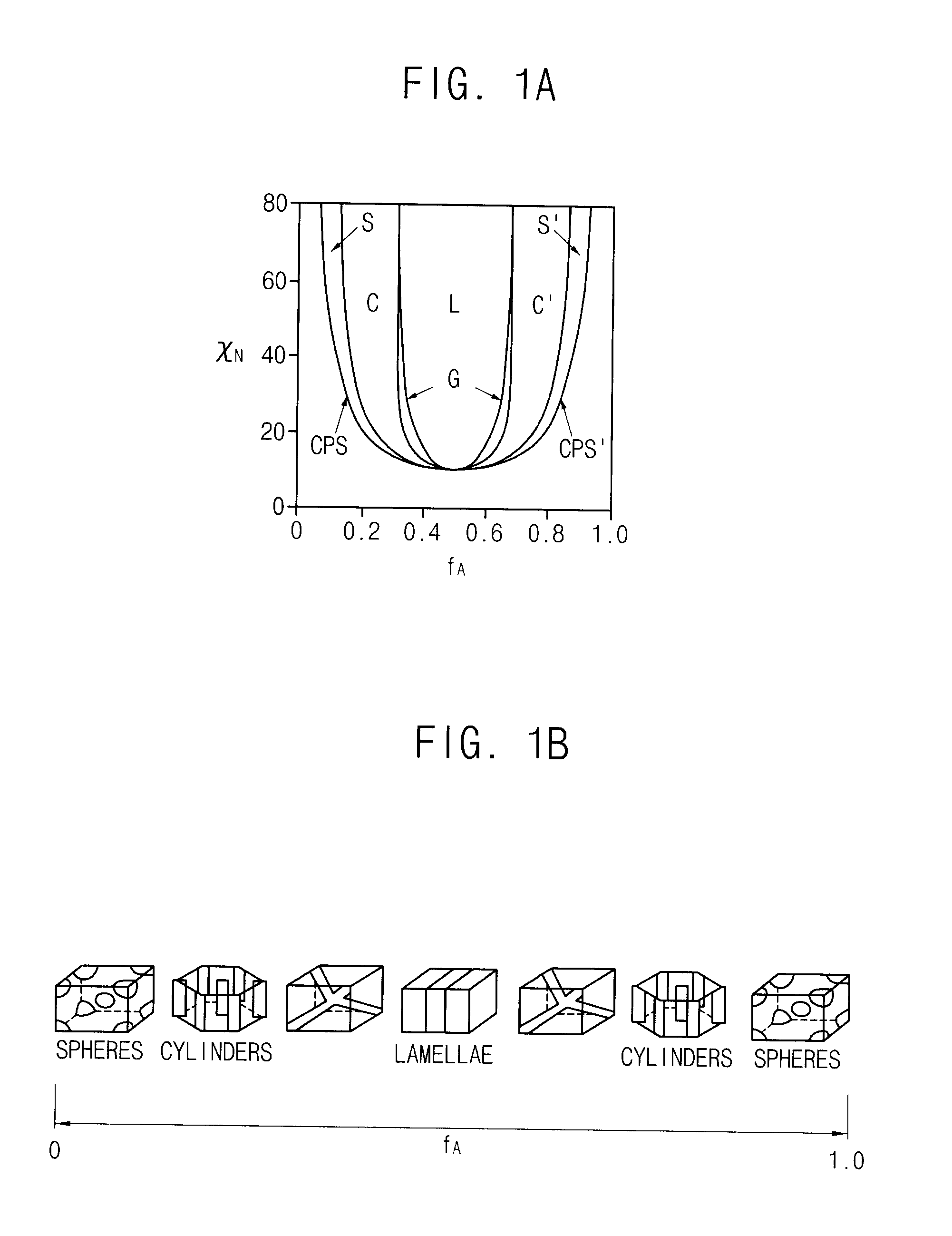
[0071]Referring to FIG. 2, a first nano-structure NS1 includes a plurality of first nano-blocks NB1 and a plurality of second nano-blocks NB2, which are formed on a base substrate 110. The nano-structure formed according to the embodiment is described in Korean Patent Applications No. 2008-126655, which is commonly assigned to Korea Advanced Institute of Science and Technology and the assignee of the application. The nano-structure formed according to the embodiment has a lamellae shape as illustrated in FIG. 1B.
[0072]The first nano-blocks NB1 extend in a first direction D1 on the base substrate 110, and are arranged in a second direction D2 different from the first direction D1 to be spaced apart from each other. The second direction D2 may be perpendicular to the first direction D1. The second nano-blocks NB2 extend in the first di...
embodiment 2
Nano-Structure
[0127]FIG. 6 is a perspective view illustrating a nano-structure manufactured according to an example embodiment of the present invention.
[0128]Referring to FIG. 6, a second nano-structure NS2 includes a first nano-block NB1 and a second nano-block NB2. The second nano-structure NS2 may further include a chemical pattern layer 122. The second nano-structure NS2 of the embodiment may have a cylindrical shape as illustrated in FIG. 1B.
[0129]The first nano-block NB1 has a cylindrical shape having a bottom surface contacting the chemical pattern layer 122. The second nano-block NB2 is disposed between adjacent first nano-blocks NB1 to surround the first nano-block NB1. The first nano-block NB1 includes PMMA, and the second nano-block NB2 includes PS. In a different aspect, the second nano-block NB2 may be a substrate surrounding the first nano-block NB1.
[0130]The chemical pattern layer 122 is substantially the same as the chemical pattern layer illustrated in FIG. 2. Thus,...
embodiment 3
Nano-Structure
[0143]FIG. 8 is a perspective view illustrating a nano-structure manufactured according to an example embodiment of the present invention.
[0144]Referring to FIG. 8, a third nano-structure NS3 includes a first nano-block NB1 and a second nano-block NB2. The third nano-structure NS3 may further include a photoresist pattern 134 and a neutral layer 120, which are sequentially formed on a base substrate 110. The neutral layer 120 is substantially the same as the neutral layer illustrated in FIG. 3A. Thus, the repeated explanation may be omitted.
[0145]The first and second nano-blocks NB1 and NB2 extend in a first direction D1 on the base substrate 110, and are repeatedly arranged in a second direction D2 different from the first direction D1. The second direction D2 may be substantially perpendicular to the first direction D1. The third nano-structure NS3 may be substantially the same as the first nano-structure NS1 illustrated in FIG. 2 except that the third nano-structure...
PUM
 Abstract
Description
Claims
Application Information