

Systems and methods for identifying landmarks on orthopedic implants
- Summary
- Abstract
- Description
- Claims
- Application Information
AI Technical Summary
Benefits of technology
Problems solved by technology
Method used
Image

Examples
first embodiment
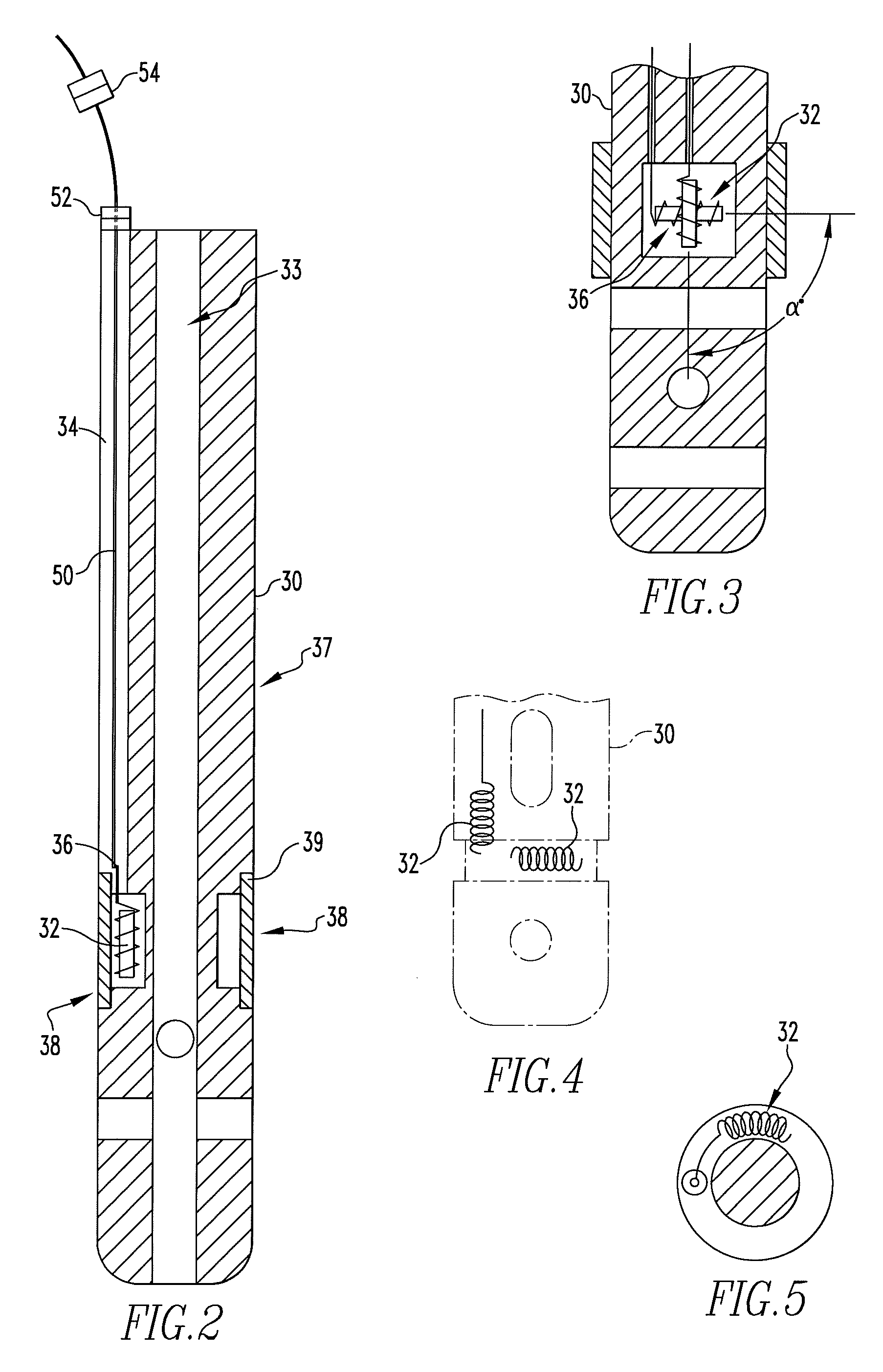
[0099]FIG. 3 illustrates the first sensor 32. The first sensor 32 may include two coils cross-layered to one another and having an angle alpha.
second embodiment
[0100]FIGS. 4 and 5 illustrate the first sensor 32. The first sensor may include two coils generally orthogonal to one another in order to establish the orientation and position in the six degrees of freedom. A first coil may be oriented along the length of the implant 30. The second coil may be oriented either wrapped around the circumference of the implant, for example in a groove, or along the radius of the implant 30. In addition, while it is preferred to have the coils perpendicular to one another, other orientations may be used, although the mathematics may be more complex. Further, the coils may be oriented spirally around the implant 30. Such an orientation may allow two coils to be placed perpendicular to each other with both coils placed along both the length of the implant and along the circumference of the implant 30.
[0101]FIGS. 6-8 illustrate a second embodiment of the orthopedic implant assembly 60. The orthopedic implant assembly 60 may include the implant 30. In the ...
PUM
 Abstract
Description
Claims
Application Information