Transformer transporting/assembling method and u-shaped iron core assembling device

a technology of assembling device and transformer, which is applied in the field of transformers, can solve the problems of reducing the installation space, reducing the installation period, and reducing the installation cos

Active Publication Date: 2010-06-24
KK TOSHIBA
View PDF1 Cites 6 Cited by
  • Summary
  • Abstract
  • Description
  • Claims
  • Application Information

AI Technical Summary

Benefits of technology

[0017]According to the present invention, it is possible to reduce the installation space, installation period, and installation cost in a transformer transporting / assembling method.

Problems solved by technology

However, there exist the following problems in the above example.
Thus, it takes more time to install the entire transformer than in the case of a general disassembled transportation transformer where the iron core is transported in the form of the U-shaped iron core by the time length required for assembling the U-shaped iron core at the installation site.
For example, it is necessary to open the roof of the assembling room when the iron core is carried in the assembling room, so that the carry-in work cannot be performed in the case of rain, delaying the installation.
The rental fee, etc., of such a tow truck with large hoisting capacity is high, and there is no other way but to rent a tow truck whose per-unit time rental fee is high in order to assemble the U-shaped iron core, causing increase in cost.
More concretely, at least one 200 ton-class heavy device and one 100 ton-class heavy device are required, requiring a large installation space and a high rental fee, which increases cost.

Method used


Image

  • Transformer transporting/assembling method and u-shaped iron core assembling device
  • Transformer transporting/assembling method and u-shaped iron core assembling device
  • Transformer transporting/assembling method and u-shaped iron core assembling device

Examples


first embodiment

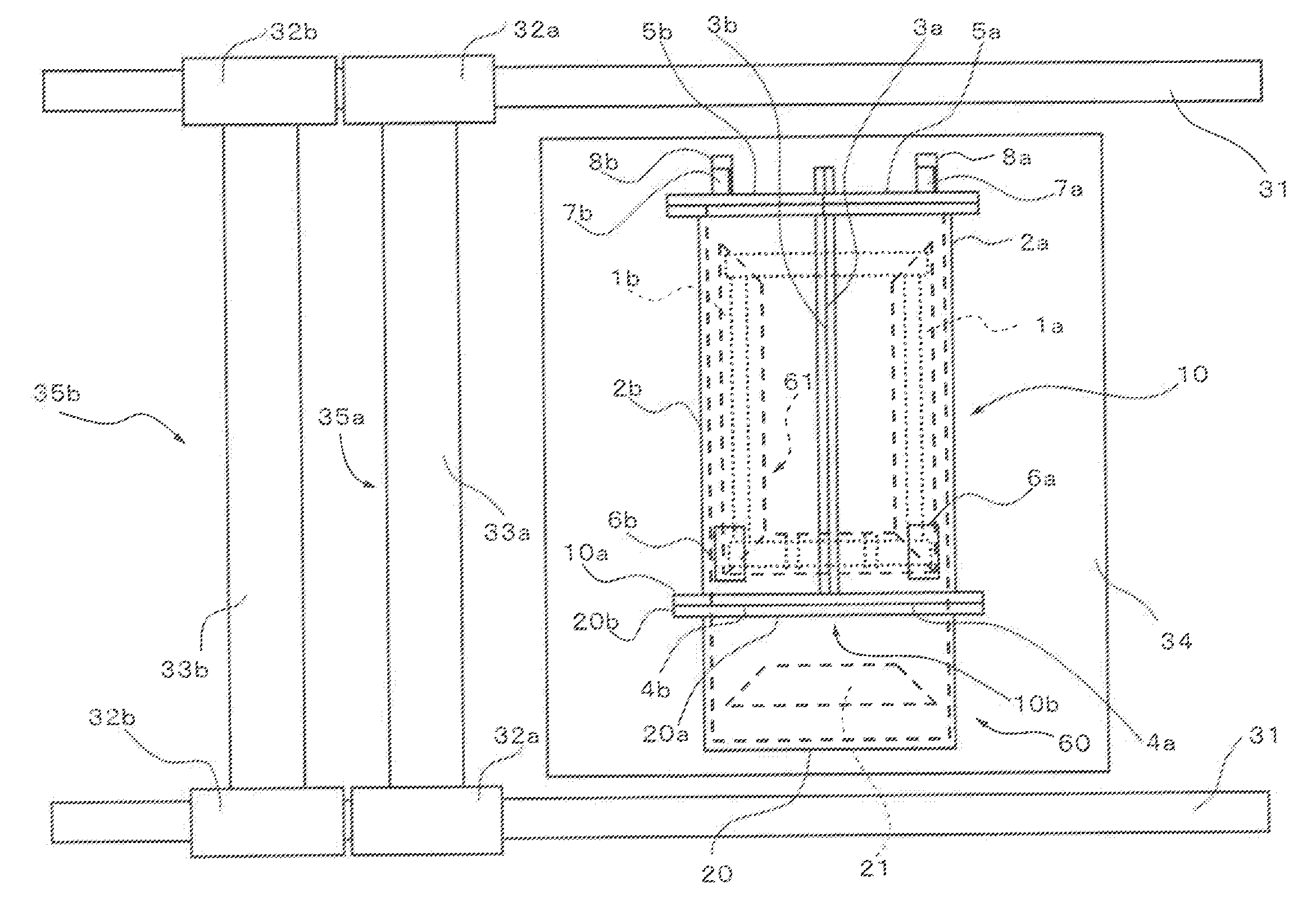
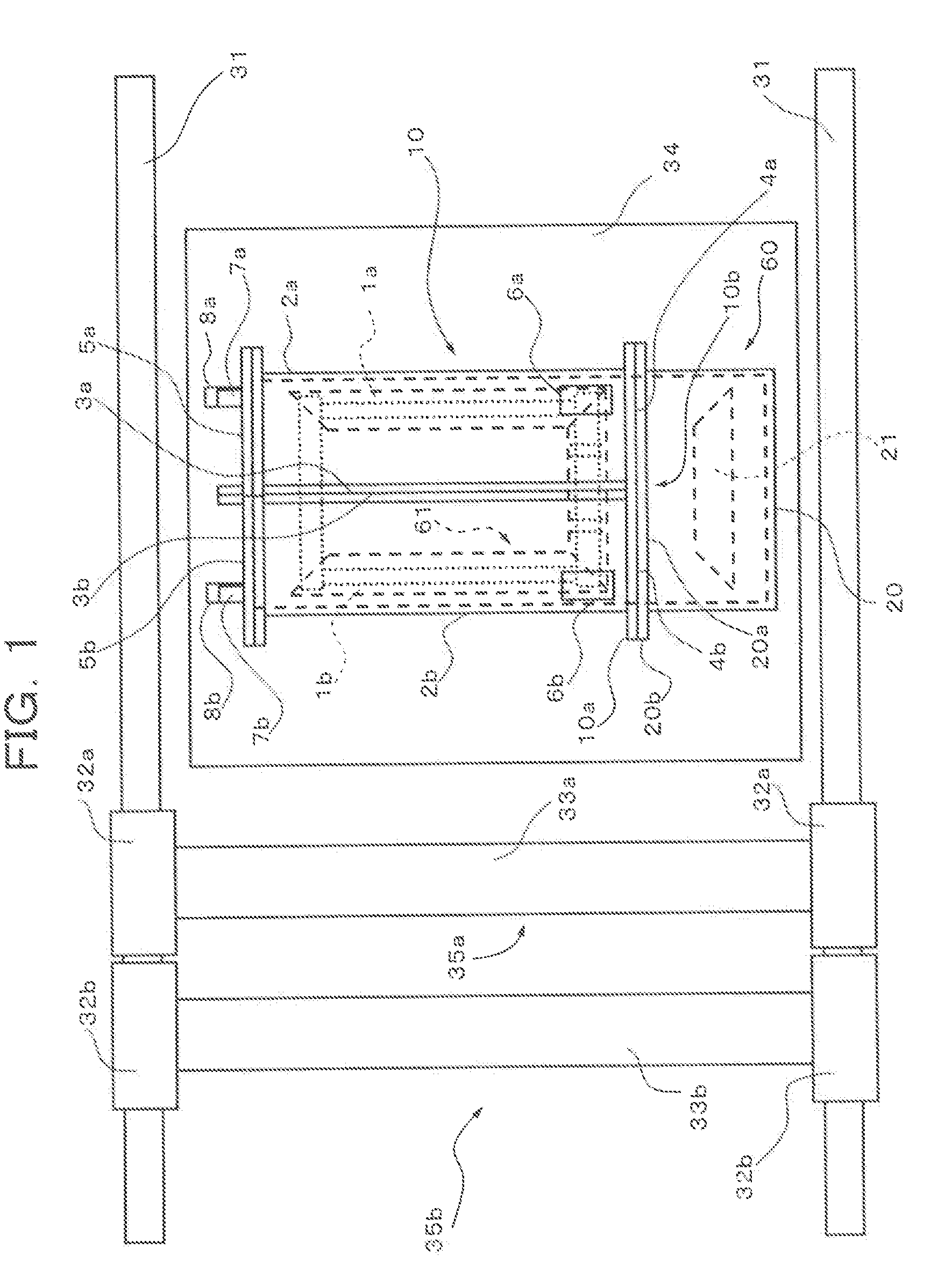
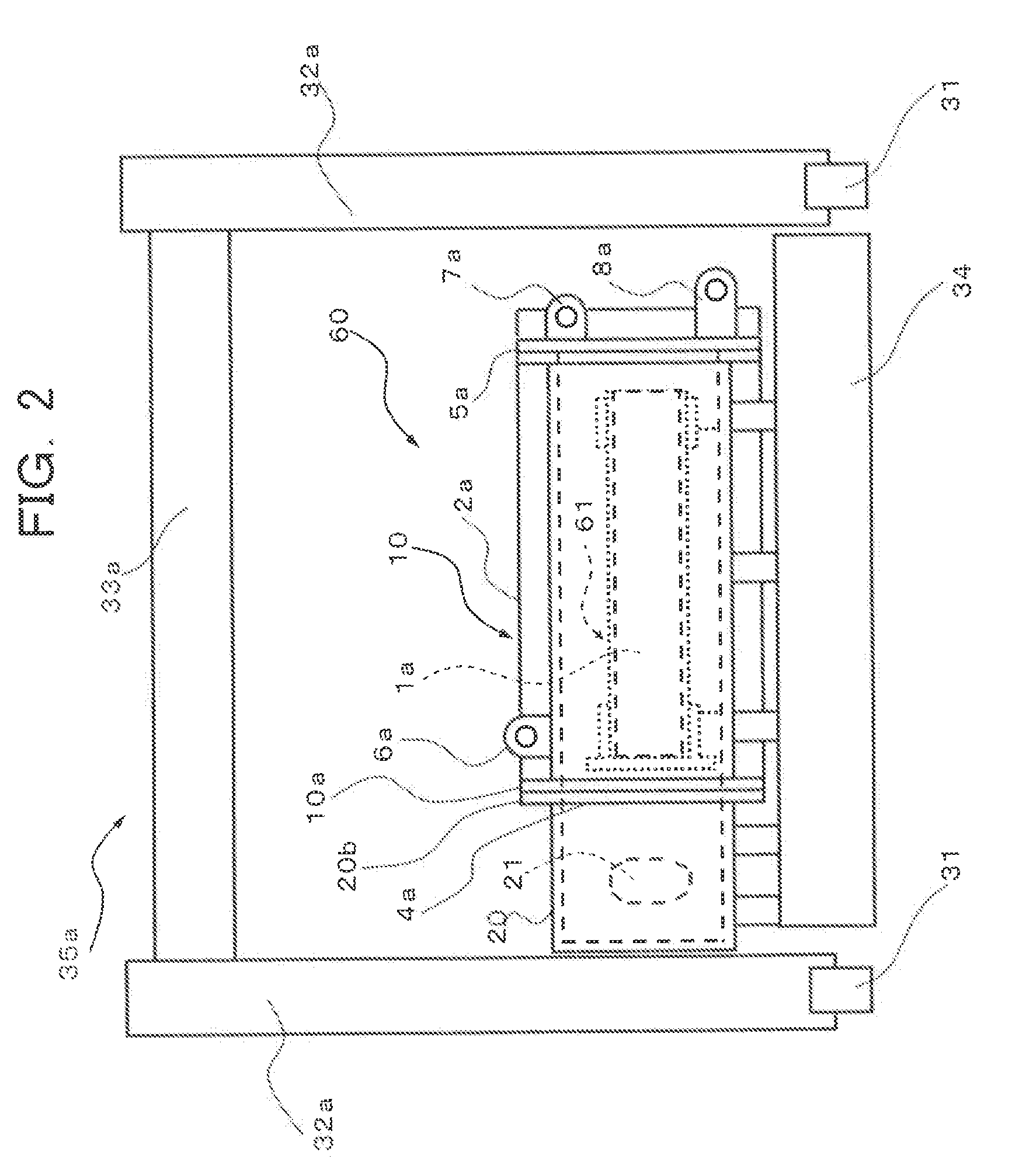
[0039]FIG. 1 is a schematic plan view of an example of a first portal lifter 35a, a second portal lifter 35b, and a U-shaped iron core assembling tank 60 according to a first embodiment, which schematically shows a state where the U-shaped iron core assembling tank 60 housing a U-shaped iron core 61 is temporarily disposed on an assembling stand 34. FIG. 2 is a schematic front view of FIG. 1.

[0040]The U-shaped iron core 61 constituting a transformer, etc. includes a first leg iron core 1a, a second leg iron core 1b, a lower-yoke iron core 21, and the like.

[0041]The first leg iron core 1a, the second leg iron core 1b, and the lower-yoke iron core 21 are transported to an installation site of a transformer, etc. by a first leg iron core tank 2a, a second leg iron core tank 2b, and a lower-yoke iron core transporting tank (not shown), respectively. At this time, the first leg iron core 1a and the second leg iron core 1b are housed in the first leg iron core tank 2a and the second leg i...

second embodiment

[0067]FIG. 9 is a schematic plan view of an example of the first portal lifter 35a, the second portal lifter 35b, and the erection tank 10 according to a second embodiment of the transformer transporting / assembling method of the present invention, which schematically shows a state where the erection tank 10 is temporarily disposed on the assembling stand 34. FIG. 10 is a schematic front view of FIG. 9.

[0068]In the present embodiment, hoisting pins 44 are each formed by welding in the center of one side surface of the erection tank 10 at a portion slightly father from the erection tank bottom plate 10c than the rotational center of the erection tank 10 is from the erection tank bottom plate 10c. Further, hoisting rings 45 are each fitted to the hoisting pin 44 by, e.g., interference fitting. The first portal lifter 35a has a configuration in which the first beam 33a and the hoisting ring 45 are connected to each other by the wire 43 so as to lift the erection tank 10.

[0069]The transf...

third embodiment

[0075]FIG. 14 is a schematic front view of an example of the first portal lifter 35a and the erection tank 10 according to a third embodiment of the transformer transporting / assembling method of the present invention, which schematically shows a state where the erection tank 10 is temporarily disposed on the assembling stand 34. In the present embodiment, connection seats 48 are mounted at the lower portion of the erection tank 10 in addition to the components of the second embodiment. The connection seats 48 are respectively connected to traveling carriages 50 each of which can travel on the assembling stand 34 by a connection pin 49, etc.

[0076]The transformer transporting / assembling method according to the present embodiment will be described below. First, as in the case of the first embodiment, the first portal lifter 35a and the second portal lifter 35b are assembled, the assembling stand 34 is disposed between the traveling rails 31, and the erection tank 10 according to the pr...


PUM

PropertyMeasurementUnit
weightaaaaaaaaaa
distanceaaaaaaaaaa
flexibleaaaaaaaaaa

Abstract

A transformer transporting/assembling method comprises a transportation step of transporting a U-shaped iron core with an iron plate horizontally extending to a place near an installation site and an erection step of erecting the U-shaped iron core together with an erection tank from a state that the iron plate extends horizontally to a state that the iron plate extend vertically, with the U-shaped iron core contained in the erection tank. The erection step includes a sub-step in which a portal lifter composed of two booms which are vertically expandable and parallel movable with a predetermined distance therebetween and between which the erection tank is disposed and a beam horizontally connecting the two booms and vertically moved as the booms expands or contracts is used, the beam supports the erection tank through a flexible member at predetermined support portions, and the beam is vertically moved by expanding/contracting the booms.

Description

CROSS REFERENCES TO RELATED APPLICATIONS[0001]This application is a continuation-in-part (CIP) application based upon the International Application PCT / JP2008 / 002360, the International Filing Date of which is Aug. 29, 2008, the entire content of which is incorporated herein by reference, and claims the benefit of priority from the prior Japanese Patent Application No. 2007-231010, filed in the Japanese Patent Office on Sep. 6, 2007, the entire content of which is incorporated herein by references.BACKGROUND OF THE INVENTION[0002]The present invention relates to a transformer transporting / assembling method in a transformer transported in a disassembled condition and a U-shaped iron core assembling device.[0003]In recent years, voltage to be supplied to a transmission system increases with an increase in electric power demand. Accordingly, the capacity, size, and weight of static induction electric appliances, such as transformers, used for power transmission / transformation increase.[...

Claims


Application Information

Patent Timeline
Patent Type & Authority Applications(United States)
IPC IPC(8): H01F7/06B23P19/00
CPCH01F27/266H01F41/00Y10T29/49002Y10T29/49073Y10T29/49071Y10T29/4902Y10T29/5313
Inventor SHIBATA, KEIGOSUGIHARA, MASAKI
Owner KK TOSHIBA
Why Eureka
Try Eureka