Novel solid materials and method for co2 removal from gas stream

a technology of solid materials and gas stream, which is applied in the direction of physical/chemical process catalysts, organic compounds/hydrides/coordination complex catalysts, and separation processes, etc., can solve the problems of reducing the investment cost of the system and reducing the pressure drop experienced by the process gas passing through the absorption vessel, so as to achieve efficient removal of carbon dioxide

Inactive Publication Date: 2010-06-24
GENERAL ELECTRIC TECH GMBH
View PDF12 Cites 48 Cited by
  • Summary
  • Abstract
  • Description
  • Claims
  • Application Information

AI Technical Summary

Benefits of technology

The technical effect of this patent is that it provides an effective way to remove carbon dioxide from exhaust gases produced by burning fuels.

Problems solved by technology

This patent discusses methods for reducing carbon dioxide emissions from exhaust gases produced by burning fuels like coal or oil in power plants. Several techniques are described but they often struggle to efficiently remove enough carbon dioxide from large amounts of air that can contain up to 50% carbon dioxide.

Method used


Image

  • Novel solid materials and method for co2 removal from gas stream
  • Novel solid materials and method for co2 removal from gas stream
  • Novel solid materials and method for co2 removal from gas stream

Examples


Embodiment Construction

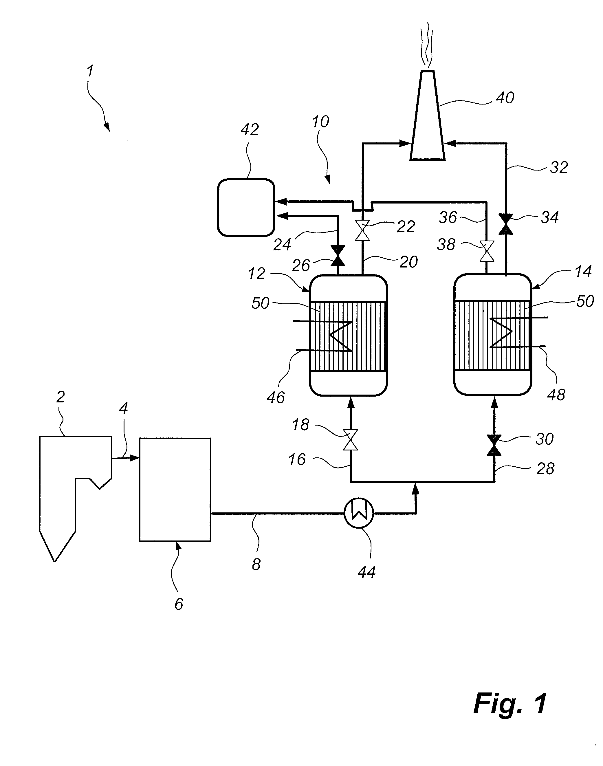
[0050]FIG. 1 is a schematic side view and illustrates a power plant 1. The power plant 1 is provided with a boiler 2 in which a fuel, such as coal, oil, peat, or waste, is combusted under generation of heat. The combustion also generates a hot process gas, which is often referred to as a flue gas. The flue gas leaves the boiler 2 via a duct 4 and is forwarded to a gas cleaning system 6. The gas cleaning system 6 is of a per se known type, and may comprise a fly ash removal device, such as an electrostatic precipitator, an example of which is illustrated in U.S. Pat. No. 4,502,872, a wet scrubber, such as that disclosed in EP 0 162 536, for removing sulphur dioxide and hydrochloric acid, and a selective catalytic reduction unit, such as that disclosed in U.S. Pat. No. 6,146,605, for removing nitrogen oxides. Hence, the flue gas leaving the gas cleaning system 6 via a duct 8 comprises mainly carbon dioxide gas, nitrogen gas, and water vapour.

[0051]The flue gas is then forwarded to a c...


PUM

PropertyMeasurementUnit
Temperatureaaaaaaaaaa
Specific surface areaaaaaaaaaaa

Abstract

A system (10) for removing carbon dioxide from a process gas generated during the combustion of a fuel comprises at least one absorption vessel (12, 14) through which the process gas may be forwarded. The absorption vessel (12, 14) is provided with a sorbent material (50) which is operative for reversibly collecting carbon dioxide from the process gas being forwarded through the sorbent material (50). The sorbent material (50) comprises at least one amine, at least one carbon dioxide activating catalyst, and at least one porous material supporting the at least one catalyst and the at least one amine.

Description


Claims


Application Information

Patent Timeline
Owner GENERAL ELECTRIC TECH GMBH
Why Eureka
Try Eureka