
Element for emission of thermal radiation

Inactive Publication Date: 2010-06-24
SYDNEY UNIV OF TECH
View PDF7 Cites 36 Cited by
  • Summary
  • Abstract
  • Description
  • Claims
  • Application Information

AI Technical Summary

Benefits of technology

[0010]The element may also comprise a structure that has projecting wall portions which are positioned so that, in use, incoming radiation from regions of the atmosphere, which are near the horizon, is substantially blocked off. It is known that for such radiation the atmospheric window is less transmissive, because the atmosphere is “thicker” for radiation traveling closer to the horizon. Being less transmissive, the atmosphere then also radiates more strongly at these wavelengths from directions close to the horizon. Consequently, avoiding that such radiation can reach the particles improves the cooling efficiency of the element. The projecting wall portions typically are reflective for the thermal radiation emitted by the particles. The structure may also comprise the above-described cover.
[0060]In one specific embodiment the cooling device comprises a concentrator such as a “CPC” concentrator or a parabolic dish or trough concentrator. In this case the projecting wall portions typically form a portion of the concentrator. For example, the cooling device may comprise a conduit for fluid that is positioned at or near a focal region of the concentrator. The conduit may comprise the particles that emit in use the thermal radiation. A fluid may be directed through the conduit so that in use the fluid is cooled. The concentrator typically is arranged so that radiation emitted form substantially all regions of the conduit is directed towards the sky by the concentrator. Further, the projecting wall portion has the added advantage that heating of the particles, and / or of the medium that is to be cooled by the particles, by a hot breeze that may in use pass over the is reduced.

Problems solved by technology

These methods have in common that they require relatively large amounts of energy, which typically are provided in the form of electrical energy.
For example, in countries which have a relatively warm climate the electrical energy required for cooling often exceeds the available electrical energy, which may result in a breakdown of a power grid.
Further, electrical energy is at this time still at least partially generated using non-renewable energy resources, for example by burning coal, which is of concern for the environment and contributes to global warming.

Method used


Image

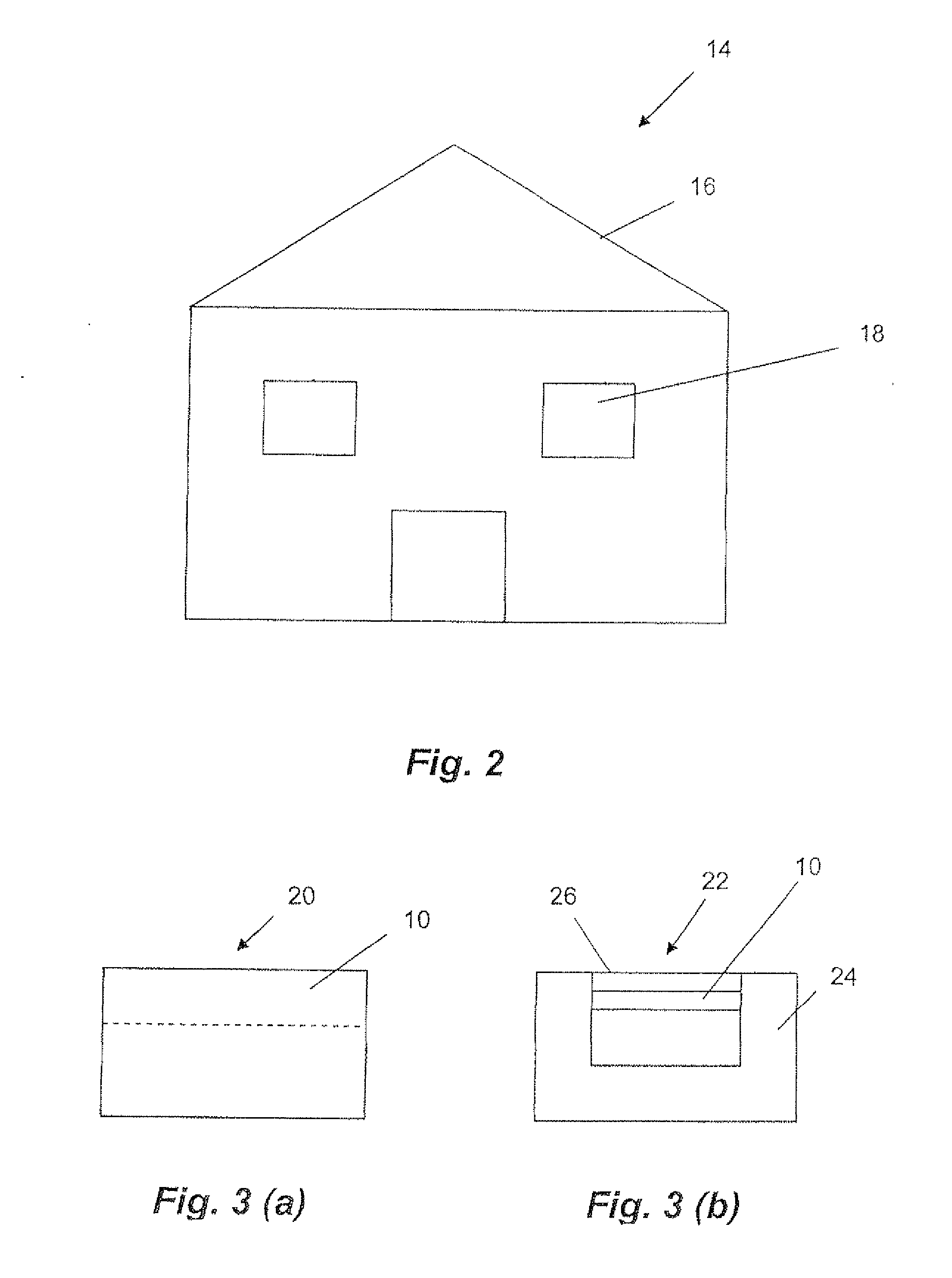
  • Element for emission of thermal radiation
  • Element for emission of thermal radiation
  • Element for emission of thermal radiation

Examples


Embodiment Construction

[0101]Generally, the element comprises particles that are arranged for emission of radiation having a wavelength within a range referred to as the “atmospheric window wavelength range”. The atmospheric window wavelength range is a wavelength range within which the absorption and emission of radiation by the atmosphere of the Earth is strongly reduced or zero. Radiation emitted from the element within that wavelength range is largely transmitted through the atmosphere to Space where the average temperature is 4 Kelvin. Further, as within that wavelength range typically very little or no radiation is received by the element, the element functions as a pump of thermal energy.

[0102]The element comprises a cooling material that is disclosed in Australian provisional patent application No 2007903673 and U.S. patent application Ser. No. 11 / 765,217. These patent applications are hereby incorporated by cross-reference. Further details of the function of the element will be discussed with ref...


PUM

PropertyMeasurementUnit
Wavelengthaaaaaaaaaa

Abstract

The present disclosure provides an element for emission of thermal radiation. The element comprises particles arranged for receiving thermal energy and emitting at least a portion of the received thermal energy in the form of the thermal radiation. The thermal radiation predominantly has a wavelength or wavelength range within an atmospheric window wavelength range in which the atmosphere of the Earth has a reduced average absorption and emission compared with an average absorption and emission in an adjacent wavelength range whereby absorption by the element of radiation from the atmosphere is reduced.

Description

FIELD OF THE INVENTION[0001]The present invention broadly relates to an element for emission of thermal radiation.BACKGROUND OF THE INVENTION[0002]Various methods are used to cool interior spaces of buildings, refrigerate food, condense water or reduce the temperature of objects. These methods have in common that they require relatively large amounts of energy, which typically are provided in the form of electrical energy. For example, in countries which have a relatively warm climate the electrical energy required for cooling often exceeds the available electrical energy, which may result in a breakdown of a power grid. Further, electrical energy is at this time still at least partially generated using non-renewable energy resources, for example by burning coal, which is of concern for the environment and contributes to global warming. Consequently, it would be advantageous if cooling could be achieved in a manner that uses less energy. There is a need for technological advancement...

Claims


Application Information

Patent Timeline
IPC IPC(8): F28F7/00
CPCC09K5/14G02B5/26F25B23/003E06B2009/2411F25D31/007F25D2331/805F28F13/18F28F2245/06
Inventor SMITH, GEOFFREY BURTON
Owner SYDNEY UNIV OF TECH
Learn More