Ac pulse arc welding control method

a pulse arc and control method technology, applied in the direction of arc welding apparatus, welding apparatus, manufacturing tools, etc., can solve the problems of large droplets, inability to achieve the 1 pulse-1 droplet transfer, and small droplet formation, etc., to achieve the effect of stable welding sta

Active Publication Date: 2010-06-24
DAIHEN CORP
View PDF7 Cites 15 Cited by
  • Summary
  • Abstract
  • Description
  • Claims
  • Application Information

AI Technical Summary

Benefits of technology

[0015]It is therefore an object of the present invention to provide an AC pulse arc welding control method which is capable of providing a stable welding state even when the electrode negative polarity current ratio is set to a larger value beyond the conventional normal range.

Problems solved by technology

Therefore, only a small part of the welding wire will melt, resulting in the formation of a very small droplet.
Such a large droplet, however, cannot be transferred completely, and some molten part will remain on the welding wire tip even at the end of the peak period Tp.
This residual droplet affects the transfer of the next droplet, making it impossible to attain the 1 pulse-1 droplet transfer.
In other words, the droplet transfer occurs at random, and the welding state becomes unstable.

Method used


Image

  • Ac pulse arc welding control method
  • Ac pulse arc welding control method
  • Ac pulse arc welding control method

Examples


first embodiment

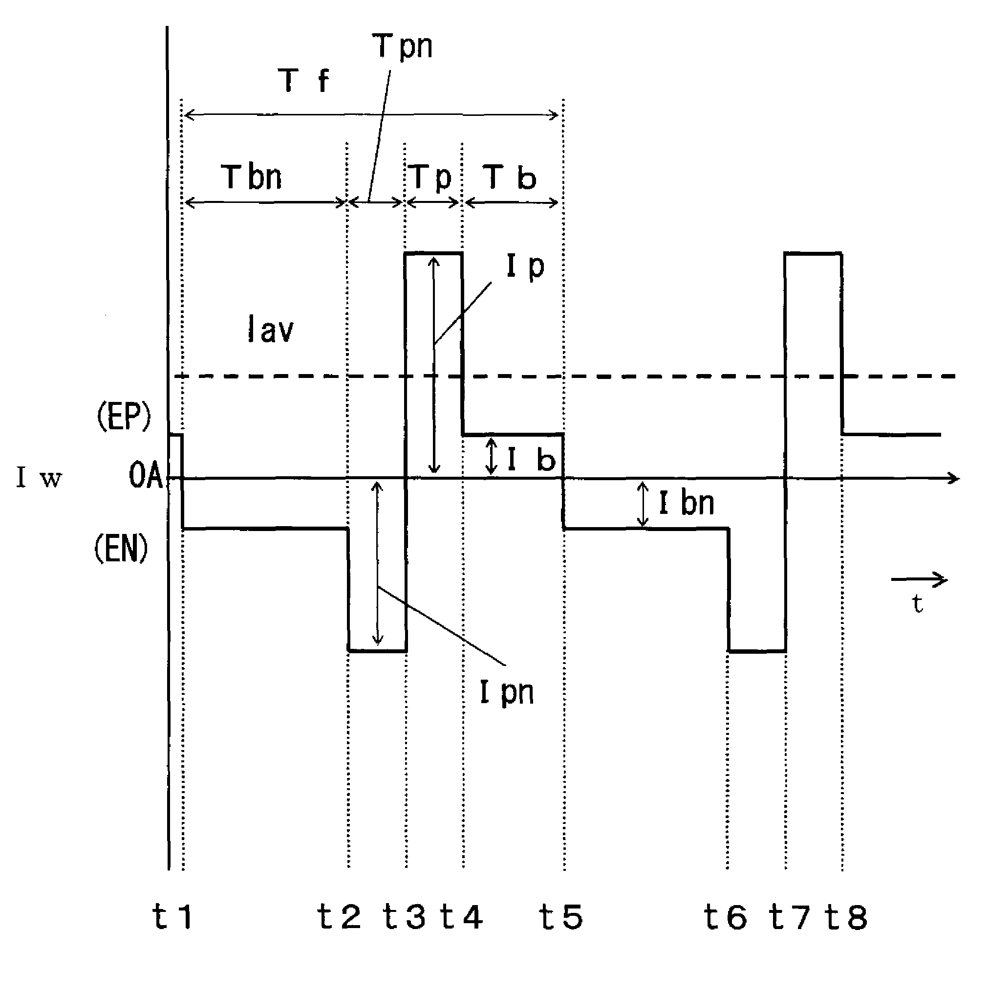
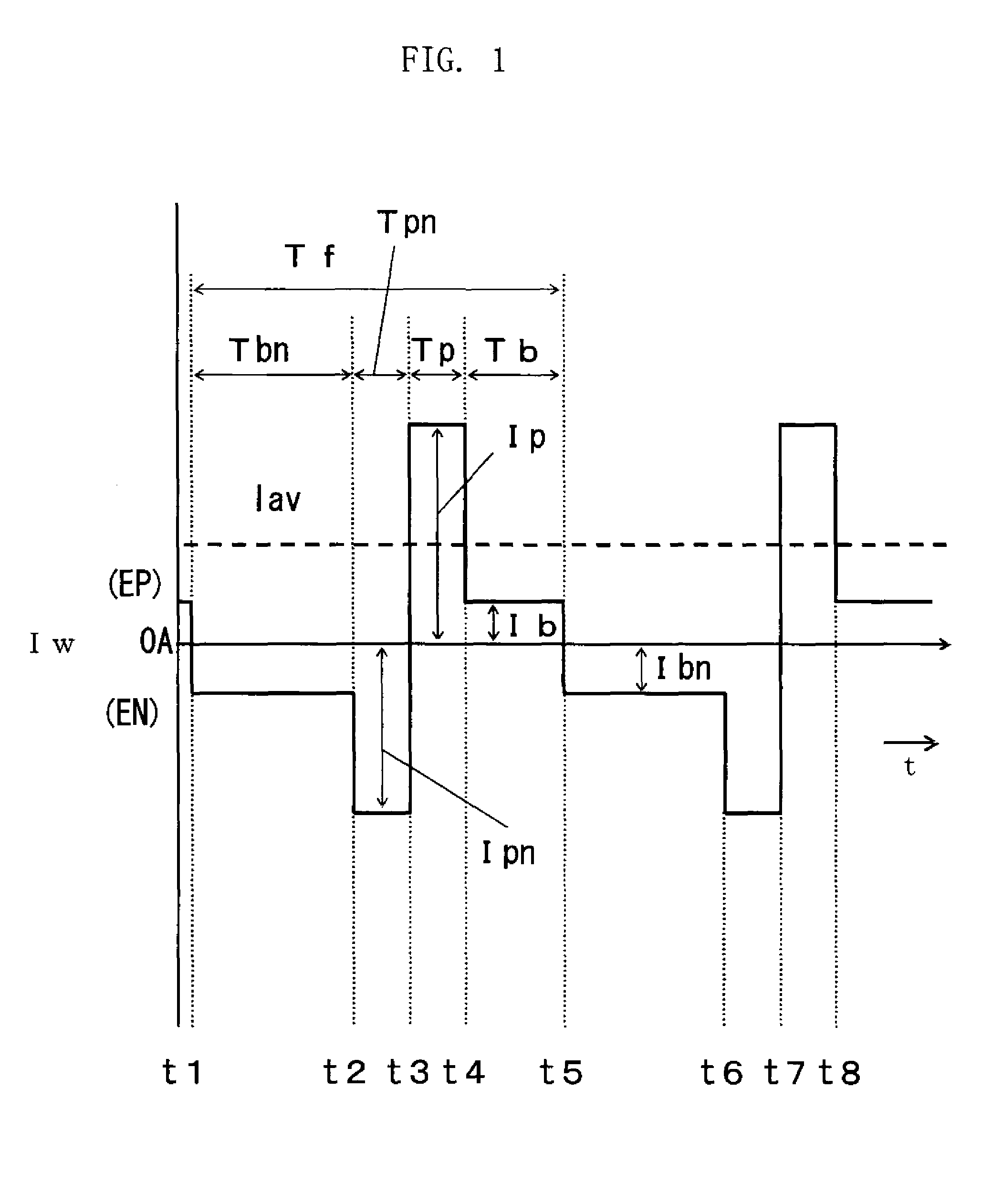
[0032]FIG. 1 is a welding current waveform chart of a welding current Iw for illustrating an AC pulse arc welding control method according to the present invention. In FIG. 1, the upper side above 0 A corresponds to the electrode positive polarity EP, while the lower side corresponds to the electrode negative polarity EN. In the illustrated case, an electrode negative polarity current ratio (to be noted below) is set to a higher value greater than the maximum value lying in a normal range (typically, 0 through 30%). In the present embodiment, as noted below, the prevention of arc breakage in polarity switching is attained by applying high voltage across the welding wire and the base metal for a very short period of time.

[0033]During an electrode negative polarity base period Tbn from time t1 to time t2, an electrode negative polarity base current Ibn the absolute value of which is smaller than a critical value (more precisely, a critical value for negative polarity) is applied. Duri...

second embodiment

[0061]As noted above, when the electrode negative polarity current ratio is set to a large value, a droplet is begun to form in the electrode negative polarity base period Tbn, and the size of the droplet to be transferred in a peak period is large. In the light of this, the present invention provides two successive peak periods, i.e., the electrode negative polarity peak period Tpn and the electrode positive polarity peak period Tp. With such two peak periods opposite in polarity, the transfer of a large-sized droplet can be performed properly.

[0062]Further, in the second embodiment, the electrode negative polarity current ratio Ren can be set to a large value more easily by removing the electrode positive polarity base period Tb (see FIG. 1) as well as by employing two peak periods opposite in polarity. In the second embodiment, the ratio Ren is changed by varying the electrode negative polarity peak period Tpn or the electrode negative polarity peak current Ipn or the electrode n...

third embodiment

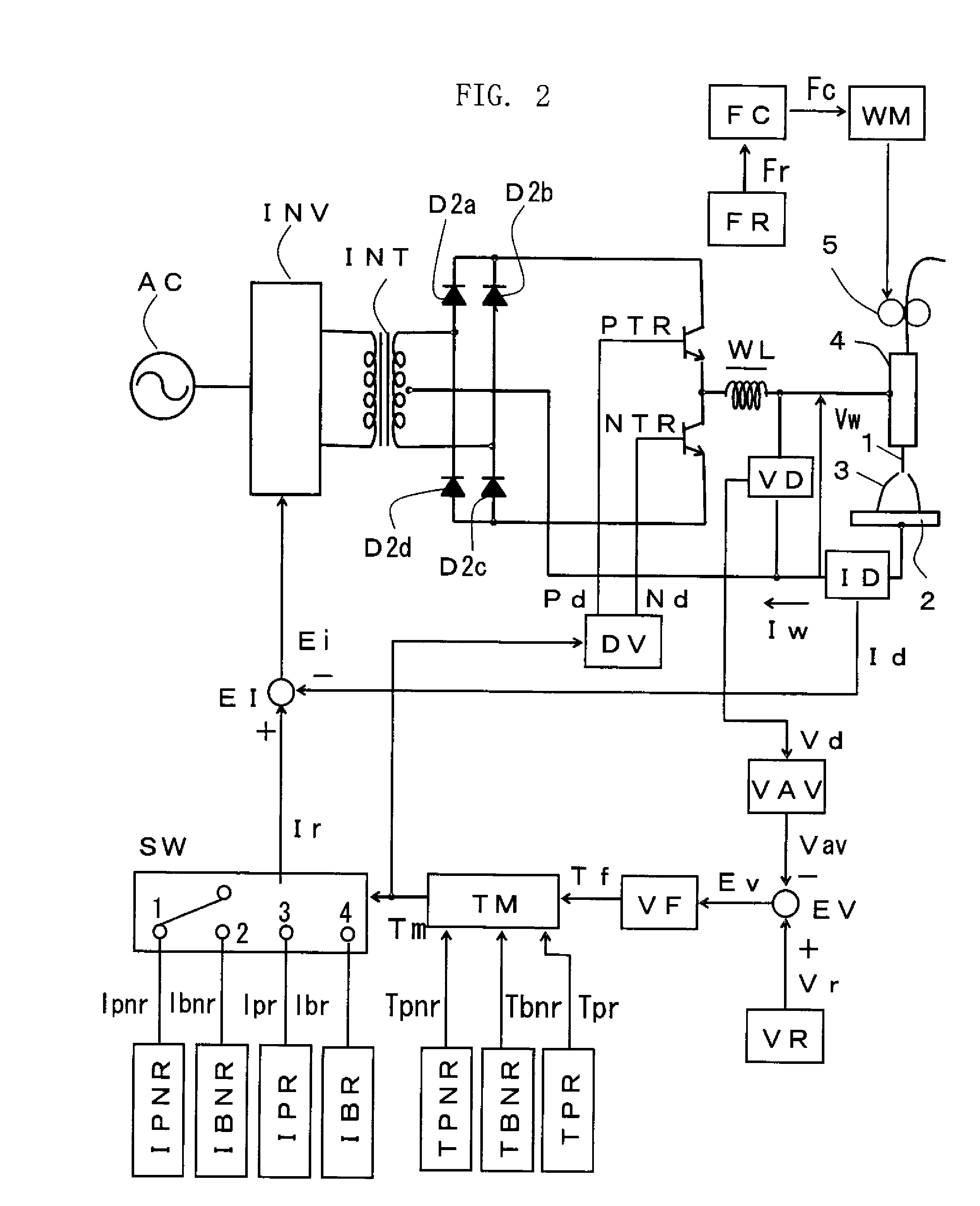
[0081]FIG. 8 is a block diagram of a welding power source for implementing the above-described AC pulse arc welding control method according to of the present invention. In FIG. 8, elements which are identical or similar to those described with reference to FIG. 2 are indicated by the same reference symbols. As seen from FIG. 8 and FIG. 2, the electrode negative polarity peak current setting circuit IPNR in FIG. 2 is replaced by another electrode negative polarity peak current setting circuit IPNR2 indicated by a rectangle of broken lines. The second electrode negative polarity peak current setting circuit IPNR2 outputs an electrode negative polarity peak current setting signal Ipnr which is an oscillating square wave having a predetermined maximum value, amplitude and duty, and oscillating at a predetermined oscillation frequency.

[0082]A timing chart of the signals in the welding power source in FIG. 8 may be basically the same as that of FIG. 3, except that the current setting sig...


PUM

PropertyMeasurementUnit
voltageaaaaaaaaaa
currentaaaaaaaaaa
currentaaaaaaaaaa

Abstract

A control method for AC pulse arc welding performed upon application of cyclic AC welding current is provided. The welding current has a cycle including an electrode negative polarity period and an electrode positive polarity period subsequent to the electrode negative polarity period. In the control method, an electrode negative polarity base current and a subsequent electrode negative polarity peak current are applied during the electrode negative polarity period. The electrode negative polarity base current has an absolute value smaller than a first critical value, and the electrode negative polarity peak current has an absolute value greater than the first critical value. Then, an electrode positive polarity peak current is applied during the electrode positive polarity period. The electrode positive polarity peak current has a value greater than a second critical value.

Description

BACKGROUND OF THE INVENTION[0001]1. Field of the Invention[0002]The present invention relates to a method for controlling AC pulse arc welding, by which stable welding is performed even when an electrode negative polarity current ratio is high.[0003]2. Description of the Related Art[0004]AC pulse arc welding proceeds by repeating cycles each consisting of an electrode positive polarity period (in which a peak current and a base current are applied) and an electrode negative polarity period (in which a base current is applied). In AC pulse arc welding, it is possible to adjust the amount of heat inputted to the base metal by adjusting the electrode negative polarity period, thereby varying the electrode negative polarity current ratio. As a result, welding with low-heat input can be performed, which enables high-quality welding with respect to thin plates. The capability of varying the electrode negative polarity current ratio also makes it possible to optimize penetration depth, wel...

Claims


Application Information

Patent Timeline
Patent Type & Authority Applications(United States)
IPC IPC(8): B23K9/09
CPCB23K9/09
Inventor SHIOZAKI, HIDEONISHISAKA, FUTOSHITAKAHASHI, NORIHITOUEZONO, TOSHIROMONDORI, HIROYASUHIROTA, SHUGONAKAGAWA, SHINICHIROUEYAMA, TOMOYUKI
Owner DAIHEN CORP
Why Eureka
Try Eureka