

Thrust bearing for a gyratory crusher and method of supporting a vertical shaft in such a crusher
a technology of gyratory crusher and bearing, which is applied in the direction of bearings, shafts and bearings, rotary bearings, etc., can solve the problems of limited withstandability of the crusher, and achieve the effects of reducing mechanical wear and power losses, reducing maintenance costs, and reducing the wear of bearing plates and power losses
- Summary
- Abstract
- Description
- Claims
- Application Information
AI Technical Summary
Benefits of technology
Problems solved by technology
Method used
Image

Examples
first embodiment
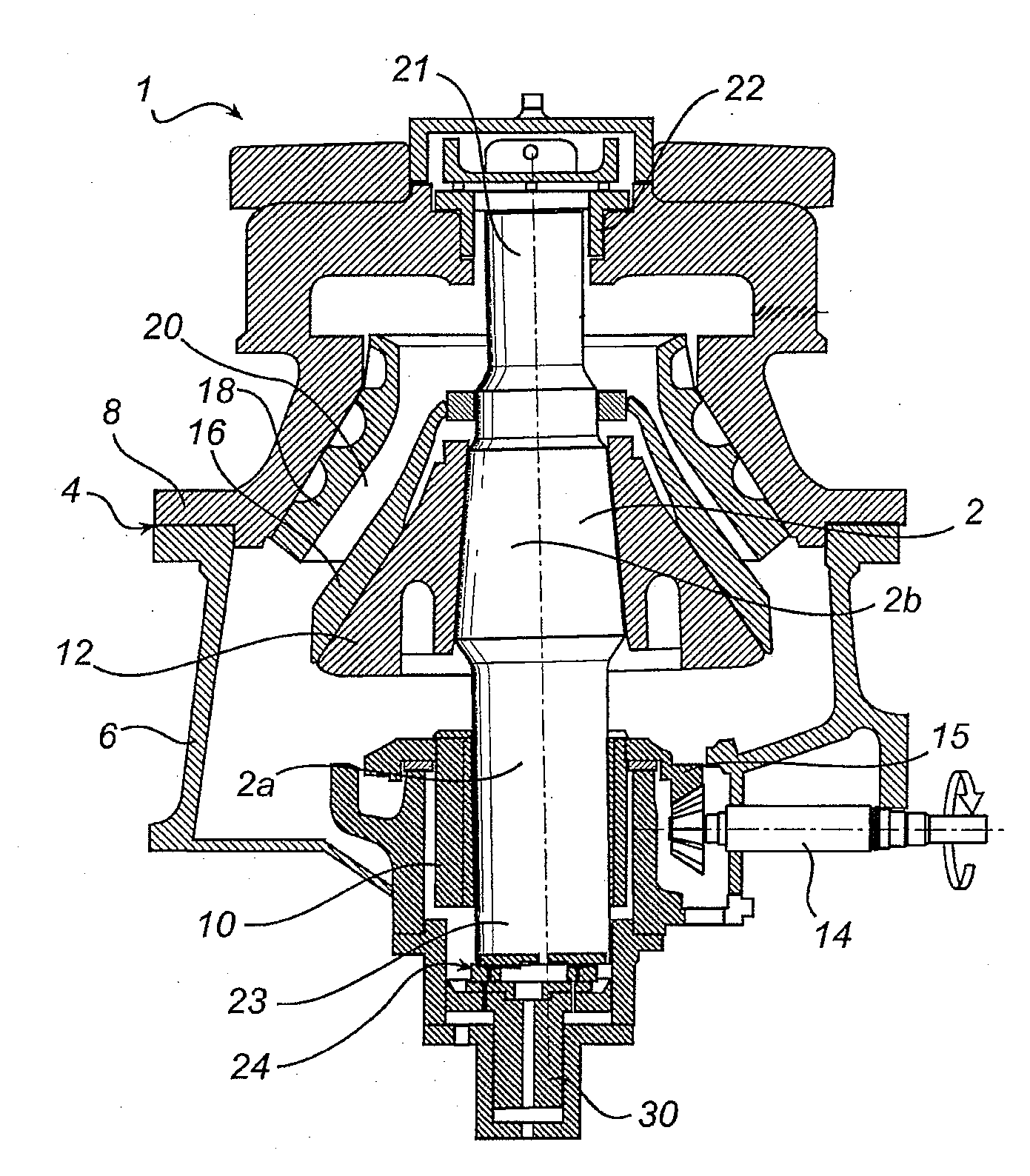
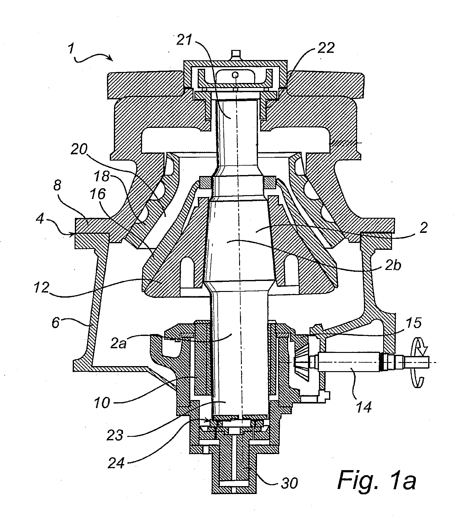
[0031]FIG. 1a illustrates schematically a gyratory crusher 1 according to a The gyratory crusher 1 has a vertical shaft 2 and a frame 4 including a frame bottom part 6 and a frame top part 8. An eccentric device in the form of an eccentric 10 is rotatably arranged about the lower portion 2a of the shaft 2. A crushing head 12 is fixedly mounted on an upper portion 2b of the shaft 2. A drive shaft 14 is arranged to rotate the eccentric 10 by means of a motor (not shown) and a gear rim 15 mounted on the eccentric 10. The vertical shaft 2 is carried at its upper end 21 in a top bearing 22 in the frame top part 8. When the drive shaft 14 rotates the eccentric 10, during operation of the crusher 1, the shaft 2 and the crushing head 12 mounted thereon will execute a gyrating movement.
[0032]A first crushing shell 16 is fixedly mounted on the crushing head 12. A second crushing shell 18 is fixedly mounted on the frame top part 8. A crushing gap 20 is formed between the two crushing shells 1...
second embodiment
[0061]Thus, the upper sliding surface 229 of the thrust bearing 224 has the same function as the upper sliding surface 129 of the second embodiment described above, for example, it serves as a hydrostatic bearing, which through the supply of oil at high pressure forms a load-bearing oil film in the upper sliding surface 229 of the thrust bearing 224. As a result the wear of the first bearing plate 226 and the third bearing plate 228 as well as the power losses are significantly reduced. The thickness of the oil gap formed in the upper sliding surface 229 is determined by the flow out from the thrust bearing 224, which in turn is determined by the constriction 266.
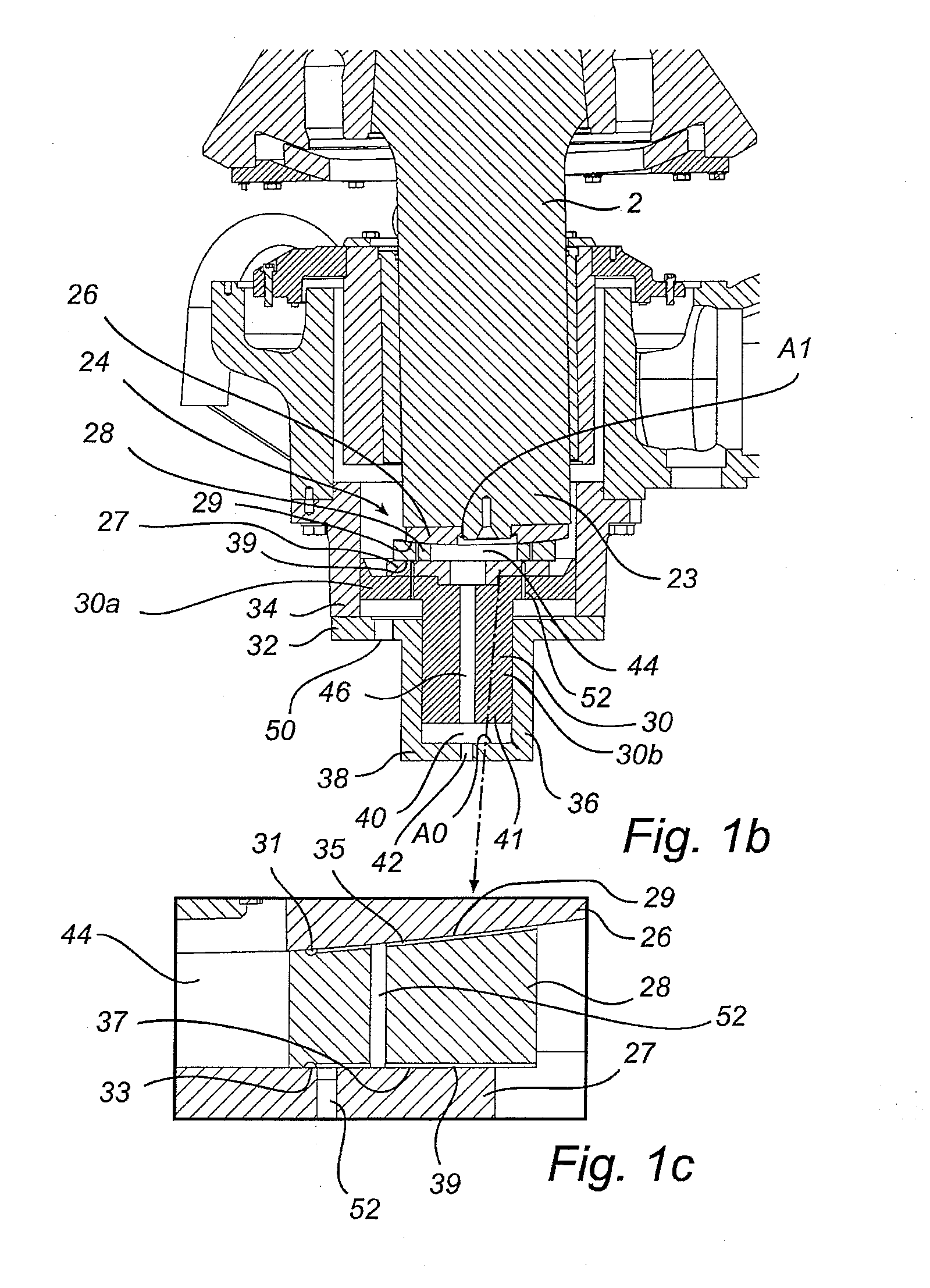
[0062]The lower sliding surface 239 of the thrust bearing 224 works in the same way as the lower sliding surface 39 of the embodiment described in FIGS. 1a-c. For the same reasons as those described previously with reference to FIG. 1c, a circular drain groove 231 and radial drain grooves 235 have been provided in the lower...
PUM
 Abstract
Description
Claims
Application Information