Light source apparatus

a technology of light source and light source, applied in the field of light source apparatus, can solve the problems of deteriorating color rendering property and inability to achieve good color rendering property, and achieve the effect of improving color rendering property and preventing the suppression of melatonin production

Active Publication Date: 2010-06-24
PANASONIC CORP
View PDF8 Cites 30 Cited by
  • Summary
  • Abstract
  • Description
  • Claims
  • Application Information

AI Technical Summary

Benefits of technology

[0022]With this configuration, wavelength components playing a role in suppressing melatonin production can be excluded by using the lens including the short wavelength cut filter provided in the resin including the optical multi-layered film covering the light emitting diode, and absorbing 480 nm or less visible light components among lights emitted by the first and the second light emitter, while the color rendering property is being kept. Further, if the above mentioned light source apparatus is employed in a light source for normal illumination, it can efficiently prevent the suppression of melatonin production.
[0023]With the light source apparatus in accordance with the present invention, a color rendering property can be improved without suppression of the melatonin production.

Problems solved by technology

In the above-mentioned examples, although melatonin suppressing efficiencies are low, there cannot be achieved a good color rendering property when lights emitted from the light emitters have sharp peak wavelengths.
Furthermore, when any one of the peak wavelengths is deviated from the desired range in one or more light emitters, the color rendering property is deteriorated.

Method used


Image

  • Light source apparatus
  • Light source apparatus
  • Light source apparatus

Examples


first embodiment

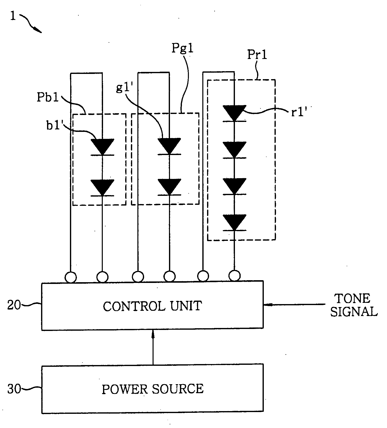
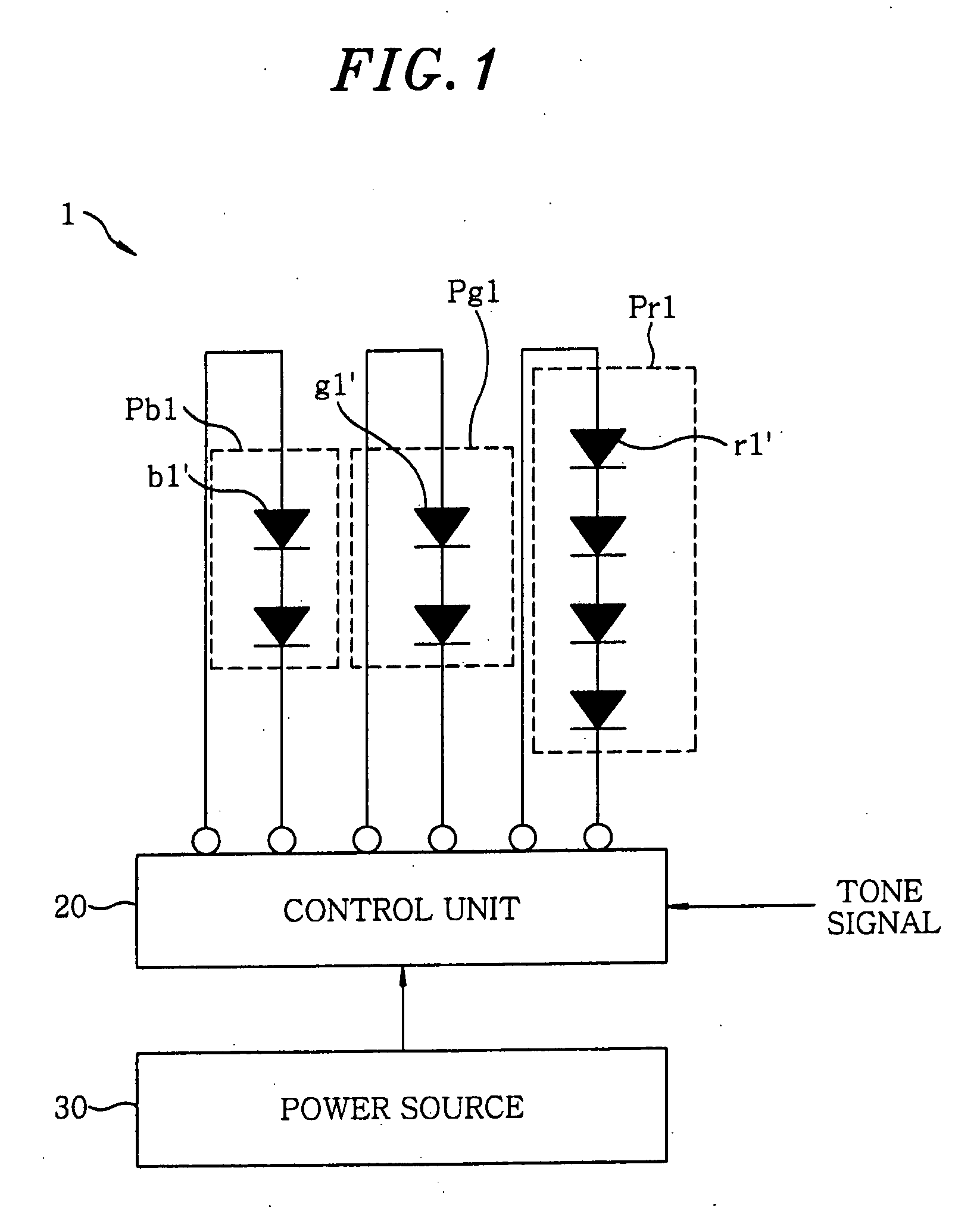
[0041]FIG. 1 schematically shows a configuration of a light source apparatus in accordance with a first embodiment of the present invention.

[0042]Referring to FIG. 1, the light source apparatus 1 includes a first, a second, and a third light emitter Pr1, Pr2, Pr3, which are provided adjacent to each other and are connected to a control unit 20 to which a tone signal to control the outputs of the light emitters Pr1 to Pr3 can be applied, respectively. The control unit 20 is supplied with power from a power source 30.

[0043]The first light emitter Pr1 includes one or more, e.g., 4, light emitting diode (LED) units r1′, each emitting a red light having a peak wavelength within the range from 600 nm to 660 nm and a wavelength range at half peak intensity wider than the range from 600 nm to 660 nm. That is, the wavelength of the peak at the maximum intensity is between 600 nm and 660 nm and the minimum and the maximum wavelength of the peak at the half maximum intensity is less than 600 n...

examples 1 and 2

[0045]Hereinafter, examples 1 and 2 of the light source apparatus 1 will be explained in which peak wavelengths of the light emitters Pr1, Pg1, Pb1 are set within the range described above.

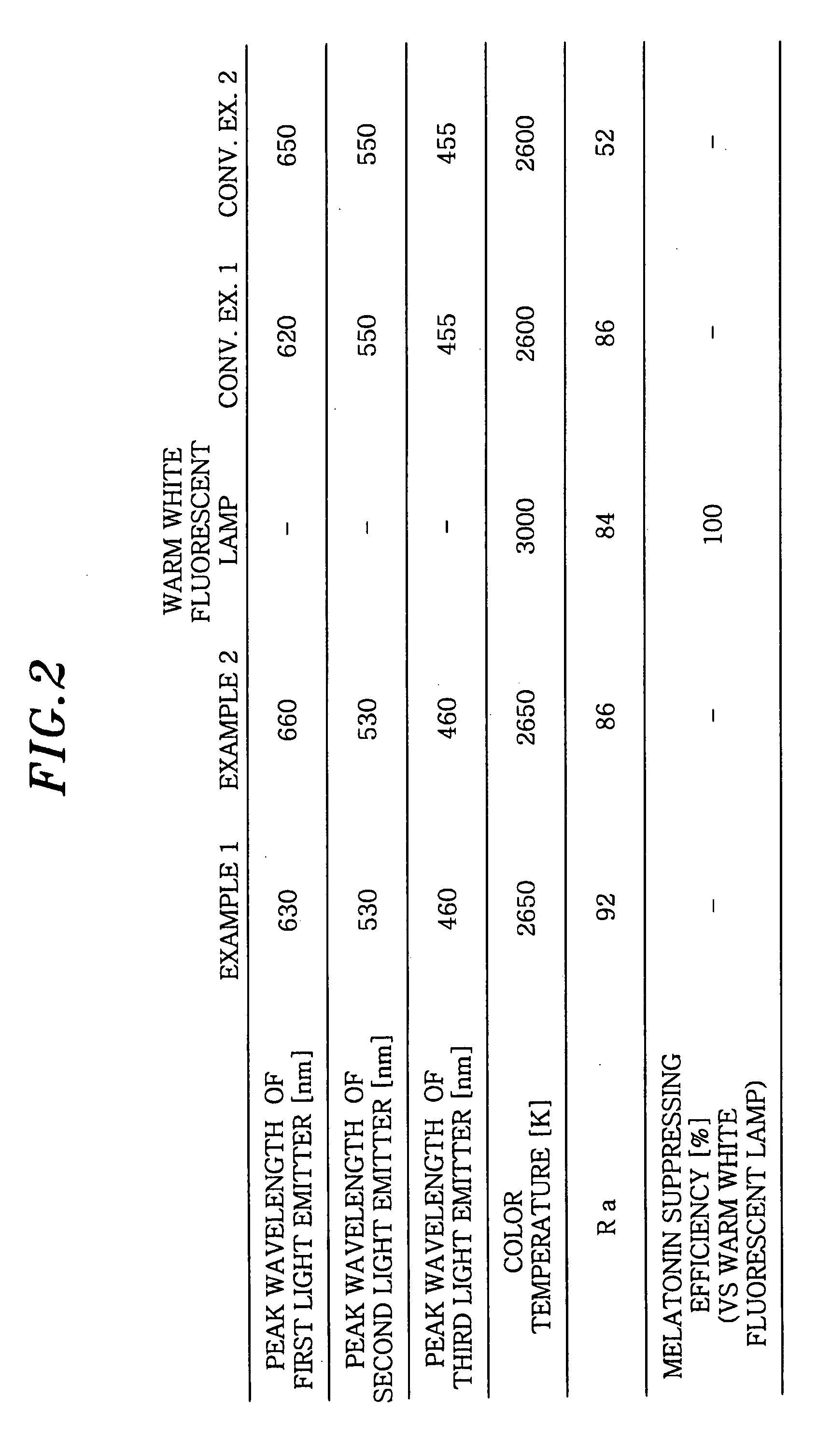
[0046]FIG. 2 is a table describing a peak wavelength for each of the light emitters Pr1, Pg1, Pb1, and a color rendering index Ra for the examples 1 and 2, together with those for the conventional examples 1, 2 as comparative examples. FIG. 3 shows spectral power distributions of lights emitted by the examples 1 and 2.

[0047]Ra is determined based on JISZ 8726. As Ra is closer to 100, a light source reproduces the colors of various objects closer to those in natural light. Generally, if Ra is 80 or more, color rendering is considered to be sufficient.

[0048]The relative melatonin suppressing efficiency indicates an efficiency suppressing melatonin secretion and is calculated by the formula shown in FIG. 12 and is expressed in percentage using a warm white fluorescent lamp as a reference.

[0049]The me...

second embodiment

[0060]FIG. 4 schematically shows a configuration of a light source apparatus 2 in accordance with a second embodiment of the present invention.

[0061]Referring to FIG. 4, the light source apparatus 2 of the second embodiment includes a first light emitter Pr2 having one or more, e.g., 4, LED units r1′, a second light emitter Pg2 having one or more, e.g., 2, LED units g1′, and a third light emitter Pb2 having one or more, e.g., 2, LED units bi′, which are disposed adjacent to each other and connected to the control unit 20, respectively.

[0062]FIGS. 5A to 5C illustrate schematic configurations of the LED units of the first, the second, and the third light emitter Pr2, Pg2, and Pb2, respectively, in accordance with the second embodiment.

[0063]Referring to FIG. 5A, each LED unit r1′ of the first light emitter Pr2 includes an LED r1, a color (or wavelength) converting unit x1 provided to cover an emitting portion of the LED unit r1′, and a short wavelength cutoff filter f1 arranged over t...


PUM


Abstract

A light source apparatus includes a first light emitter, a second light emitter, and a third light emitter. The first light emitter has a peak wavelength within the range from 600 nm to 660 nm and a wavelength range at half peak intensity wider than the range from 600 nm to 660 nm, the second light emitter has a peak wavelength within the range from 530 nm to 570 nm and a wavelength range at half peak intensity wider than the range from 530 nm to 570 nm, and the third light emitter which a peak wavelength is 420 nm-470 nm in a spectral power distribution thereof.

Description

FIELD OF THE INVENTION[0001]The present invention relates to a light source apparatus having light emitters for emitting a red, a blue, and a green light, respectively.BACKGROUND OF THE INVENTION[0002]Conventionally, there is proposed a light source apparatus for the replacement of a white light source such as an incandescent lamp, a fluorescent lamp or the like. The light source apparatus achieves a high color rendering property by using light emitting diodes emitting a red, a green, and a blue light and selecting a wavelength range of each light emitting diode in a specific range.[0003]For example, there is disclosed a light source apparatus which has a red light emitter having a peak wavelength within the range from 600 nm to 660 nm, a green light emitter having a peak wavelength within the range from 530 nm to 570 nm, and a blue light emitter having a peak wavelength within the range from 420 nm to 470 nm, as shown in a table of FIG. 14 and a spectral power distribution depicted...

Claims


Application Information

Patent Timeline
Patent Type & Authority Applications(United States)
IPC IPC(8): F21V9/16F21V9/00F21V9/40
CPCF21K9/00F21Y2113/005H05B33/0857F21K9/68F21Y2113/13F21Y2115/10H05B45/20
Inventor TODA, NAOHIRONOGUCHI, HIROKITANAKA, KENICHIRO
Owner PANASONIC CORP
Why Eureka
Try Eureka