Method and apparatus for controlling and monitoring laser power in barcode readers

a barcode reader and laser power technology, applied in the field of barcode readers, can solve the problems of laser output power, laser output power, laser output power exceeding the limits of the regulation, and the feedback signal would increase or be los

Inactive Publication Date: 2010-06-24
SYMBOL TECH INC
View PDF22 Cites 25 Cited by
  • Summary
  • Abstract
  • Description
  • Claims
  • Application Information

AI Technical Summary

Problems solved by technology

If the monitor photodiode were to lose sensitivity, fail, or to become electrically disconnected from the feedback circuit, then the feedback signal would increase or be lost, and the feedback circuit would increase the laser output power, possibly to a level exceeding regulatory limits

Method used


Image

  • Method and apparatus for controlling and monitoring laser power in barcode readers
  • Method and apparatus for controlling and monitoring laser power in barcode readers
  • Method and apparatus for controlling and monitoring laser power in barcode readers

Examples


Embodiment Construction

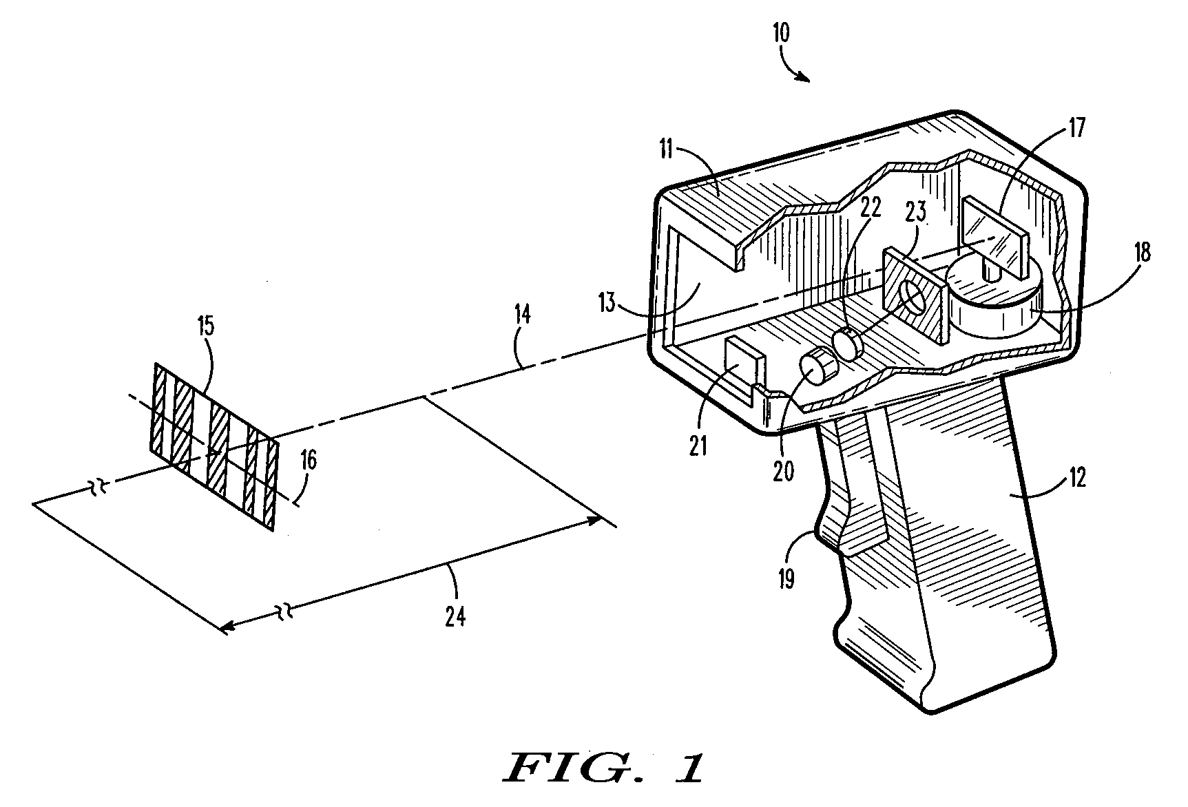
[0025]As used herein, the term “symbol” broadly encompasses not only symbol patterns composed of alternating bars and spaces of various widths as commonly referred to as bar code symbols, but also other one- or two-dimensional graphic patterns, as well as alphanumeric characters. In general, the term “symbol” may apply to any type of pattern or indicia which may be recognized or identified either by scanning a light beam and detecting reflected or scattered light as a representation of variations in light reflectivity at various points of the pattern or indicia. FIG. 1 shows an indicium 15 as one example of a “symbol” to be read.

[0026]FIG. 1 depicts a handheld laser scanner device 10 for reading symbols. The laser scanner device 10 includes a housing having a barrel portion 11 and a handle 12. Although the drawing depicts a handheld pistol-shaped housing, the invention may also be implemented in other types of housings such as a desk-top workstation or a stationary scanner. In the i...


PUM


Abstract

A method of monitoring the output power of a laser diode in a barcode reader. The method includes sampling a threshold monitoring-current that is related the driving-current passing through the laser diode during a first time period when this current is at the lasing threshold of the laser diode. The method includes generating a threshold-compensated monitoring-current by subtracting the threshold monitoring-current from the above-threshold monitoring-current. The method includes monitoring the output power of the laser diode in the barcode reader at least partially based on the threshold-compensated monitoring-current.

Description

RELATED APPLICATIONS[0001]This application is related to the following co-pending and commonly assigned U.S. patent application: Ser. No. 11 / 239,947, filed Jun. 30, 2005, titled “Laser Power Control Arrangements in Electro-Optical Readers.”FIELD OF THE DISCLOSURE[0002]The present invention relates generally to barcode readers.BACKGROUND[0003]Various electro-optical systems or readers have been developed for reading indicia such as bar code symbols appearing on a label or on a surface of an article. The bar code symbol itself is a coded pattern of graphic indicia comprised of a series of bars of various widths spaced apart from one another to bound spaces of various widths, the bars and spaces having different light reflecting characteristics. The readers function by electro-optically transforming the pattern of the graphic indicia into a time-varying electrical signal, which is digitized and decoded into data relating to the symbol being read.[0004]Typically, a laser beam from a las...

Claims


Application Information

Patent Timeline
IPC IPC(8): H01S3/13
CPCG06K7/10584H01S5/042H01S5/0683H01S5/06812H01S5/06808
Inventor GIEBEL, JAMES
Owner SYMBOL TECH INC
Why Eureka
Try Eureka