
Channel assignment method and apparatus for wavelength-division-multiplexed transmission system

a transmission system and channel assignment technology, applied in multiplex communication, instruments, optical elements, etc., can solve the problems of significant cross-interference between optical signals, deterioration of optical signals performance, and high complexity of corresponding receivers, so as to achieve the effect of suppressing interference between channels

Inactive Publication Date: 2010-06-24
ELECTRONICS & TELECOMM RES INST
View PDF3 Cites 34 Cited by
  • Summary
  • Abstract
  • Description
  • Claims
  • Application Information

AI Technical Summary

Benefits of technology

[0011]Accordingly, an object of the present invention is to suppress interference between channels.
[0012]Another object of the present invention is to improve transmission performance of channels.

Problems solved by technology

However, in transmission of optical signals of different transmission rates and different to modulation formats through an optical path, significant cross-interference between the optical signals can take place, compared to the transmission of optical signals of the same transmission rate or the same modulation format.
In this case, due to the nonlinear phenomenon such as cross-phase-modulation, then amplitude-modulated signals of NRZ or RZ format induce phase noise on phase-modulated signals of PSK or QPSK format, and thus the performance of the optical signal is deteriorated.
However, since dispersion compensation should be conducted at each channel in a circulation or mesh net in which add / drop of an optical signal can occur at each optical amplifier section, a corresponding receiver is highly complex.
However, since this method only minimizes performance deterioration by Raman crosstalk, it cannot suppress cross-phase modulation which is the main cause of performance deterioration of a phase-modulated signal, and only takes into account the transmission rate, and hence performance deterioration between channels due to the modulation formats cannot be prevented.

Method used


Image

  • Channel assignment method and apparatus for wavelength-division-multiplexed transmission system
  • Channel assignment method and apparatus for wavelength-division-multiplexed transmission system
  • Channel assignment method and apparatus for wavelength-division-multiplexed transmission system

Examples


Embodiment Construction

[0029]The following detailed description is provided to assist the reader in gaining a comprehensive understanding of the methods, apparatuses and / or systems described herein.

[0030]Various changes, modifications, and equivalents of the systems, apparatuses and / or methods described herein will suggest themselves to those of ordinary skill in the art. Descriptions of well-known functions and structures are omitted to enhance clarity and conciseness.

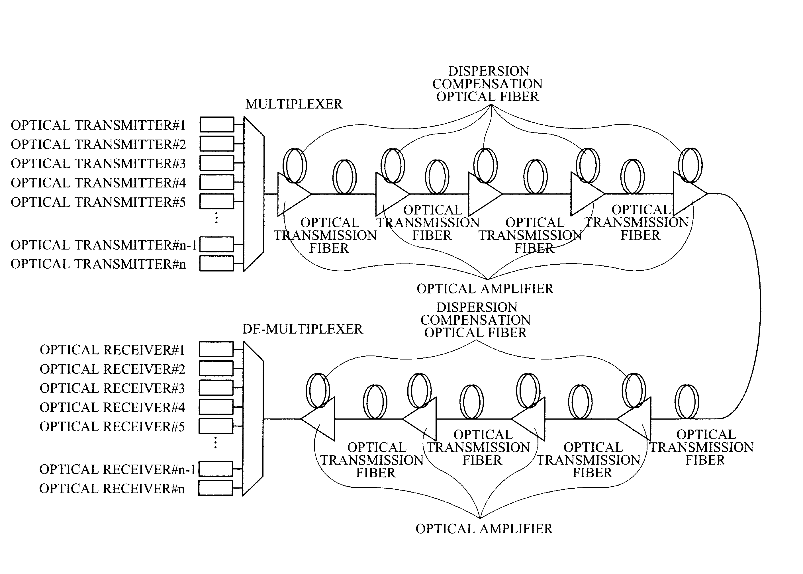
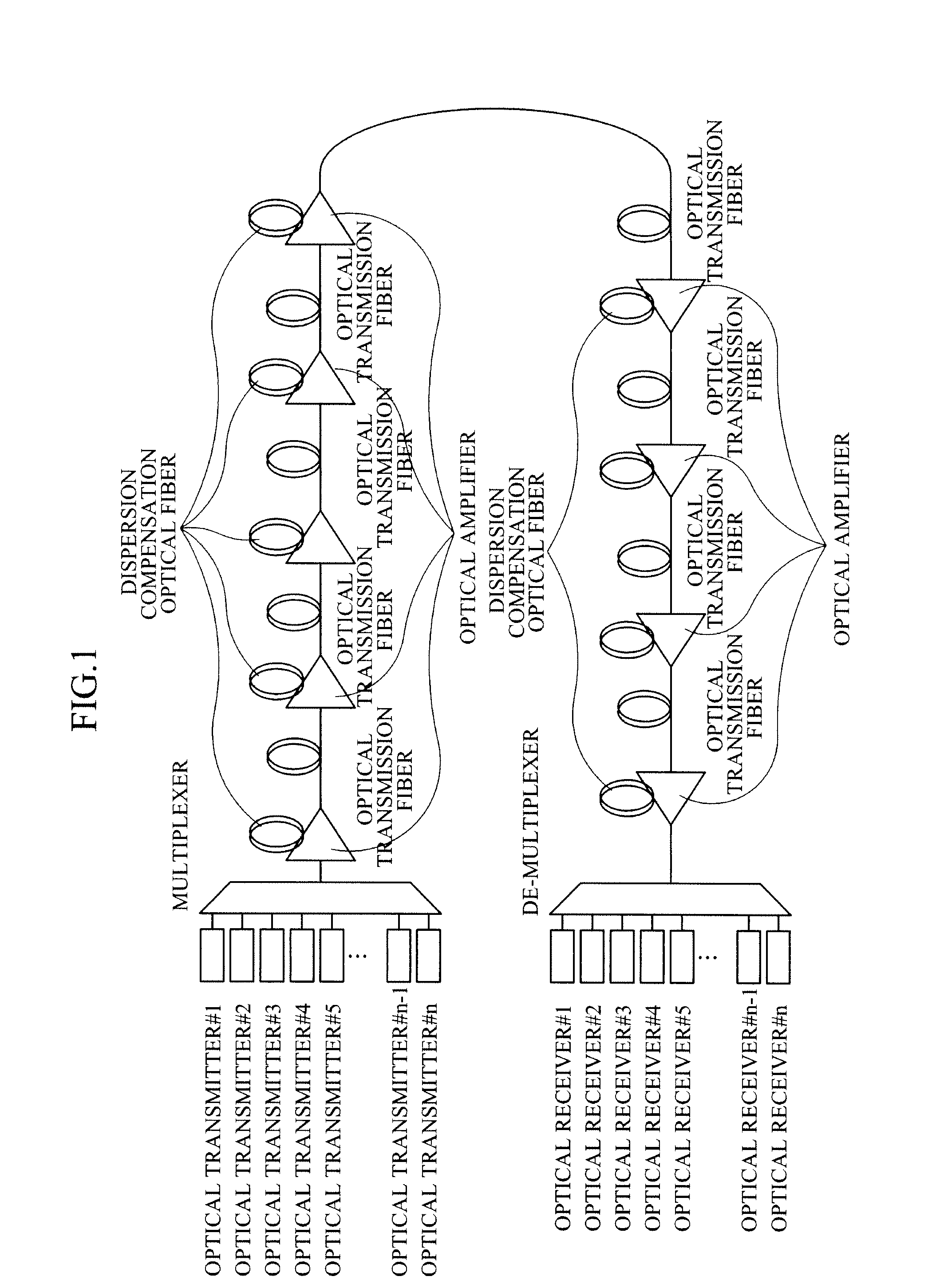
[0031]FIG. 1 is a diagram illustrating a general wavelength-division-multiplexed optical transmission system. The optical transmission system includes a transmitting part and a receiving part. The transmitting part includes a plurality of optical transmitters and at least one multiplexer. Correspondingly, the receiving part includes a plurality of optical receivers and at least one demultiplexer. The optical transmitters transmit optical signals of different wavelengths, and the signals are multiplexed by the multiplexer and then input thro...


PUM


Abstract

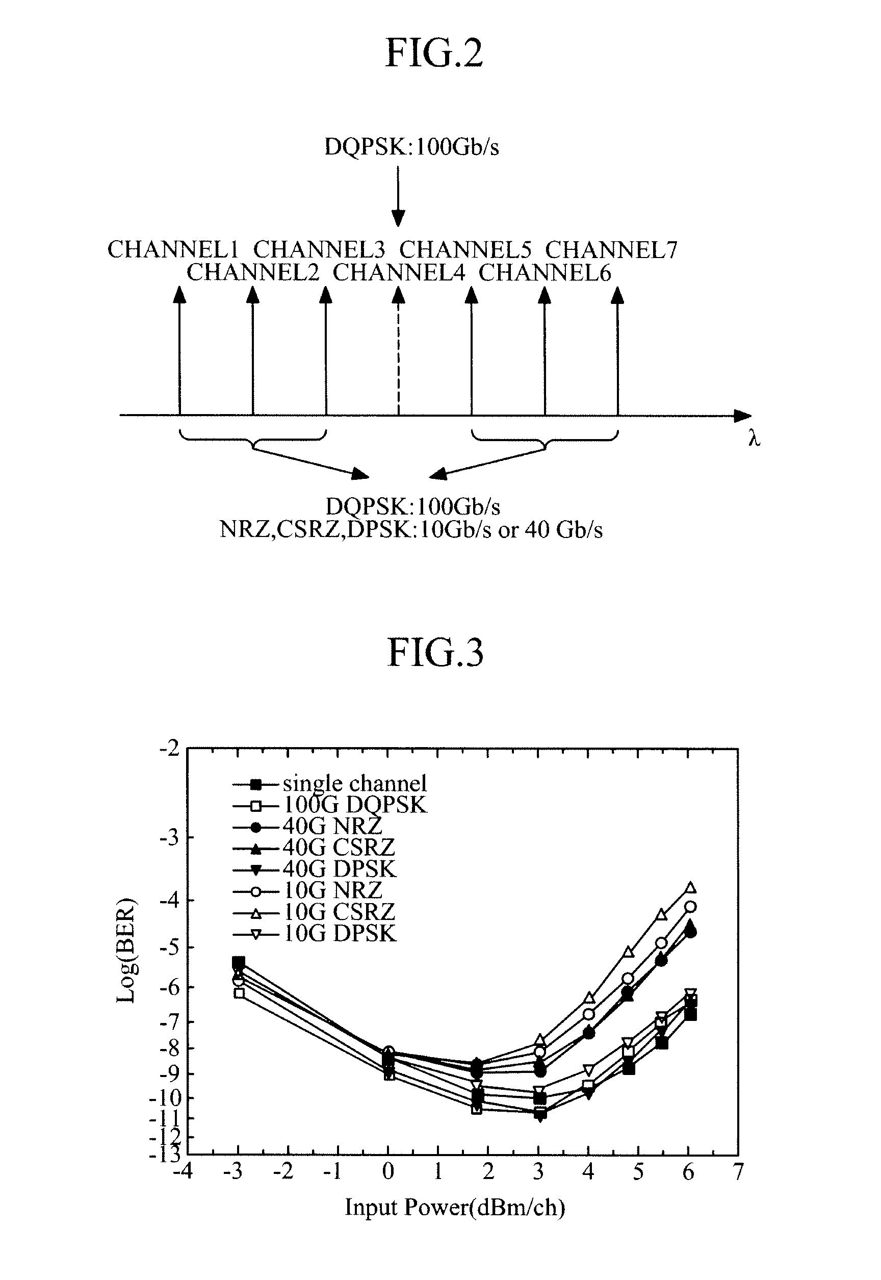
Provided is a channel assignment method in a wavelength-division-multiplexed transmission system. The channel assignment method includes obtaining information about signal modulation schemes from a plurality of optical transmitters, and assigning channels to the respective optical transmitters in consideration of the obtained information about the signal modulation schemes. Accordingly, in transmission of channels of different modulation formats, cross phase modulation is minimized, thereby reducing inter-channel interference.

Description

CROSS REFERENCE TO RELATED APPLICATION[0001]This application claims the benefit under 35 U.S.C. §119(a) of Korean Patent Application No. 10-2008-0129341, filed on Dec. 18, 2008, the disclosure of which is incorporated by reference in its entirety for all purposes.BACKGROUND[0002]1. Field[0003]The following description relates to a wavelength-division-multiplexed transmission system, and more particularly, to a channel assignment technology for a wavelength-division-multiplexed transmission system.[0004]2. Description of the Related Art[0005]With the advent of Ethernet-based services such as Internet television services and user created contents (UCC), in recent times Internet traffic has increased considerably and widening of the network is required for such services.[0006]A wavelength-division-multiplexed optical transmission system is regarded as the most efficient scheme to accommodate increases in traffic. In the wavelength-division-multiplexed optical transmission system, a num...

Claims


Application Information

Patent Timeline
IPC IPC(8): H04J14/02H04B10/2581
CPCH04B10/2557H04J14/0224H04J14/026H04J14/0257H04J14/0279H04B10/2581H04J14/02H04B10/00
Inventor CHUNG, HWAN-SEOKCHANG, SUN-HYOKLEE, SANG-SOOKIM, KWANG-JOON
Owner ELECTRONICS & TELECOMM RES INST
Learn More