Fuel cell fabrication using photopolymer based processes

a photopolymer and fuel cell technology, applied in the field of fuel cells, can solve the problems of prohibiting production volume scalability, reducing the efficiency of photopolymerization, so as to minimize production costs, minimize tooling costs, and optimize fuel cell durability

Inactive Publication Date: 2010-06-24
GM GLOBAL TECH OPERATIONS LLC
View PDF4 Cites 40 Cited by
  • Summary
  • Abstract
  • Description
  • Claims
  • Application Information

AI Technical Summary

Benefits of technology

[0010]In concordance with the instant disclosure, a structure and method for fabricating fuel cell components that optimizes fuel cell durability, minimizes tooling costs, minimizes production cost

Problems solved by technology

Undesirably, the known methods for forming each of the electrolyte membrane, the electrodes, the diffusion media, and the fuel cell plates can be costly and time consuming.
However, conventional foaming processes yield non-uniform and random (not ordered) three dimensional micros

Method used


Image

  • Fuel cell fabrication using photopolymer based processes
  • Fuel cell fabrication using photopolymer based processes
  • Fuel cell fabrication using photopolymer based processes

Examples


Embodiment Construction

[0020]The following detailed description and appended drawings describe and illustrate various embodiments of the invention. The description and drawings serve to enable one skilled in the art to make and use the invention, and are not intended to limit the scope of the invention in any manner. In respect of the methods disclosed, the steps presented are exemplary in nature, and thus, are not necessary or critical.

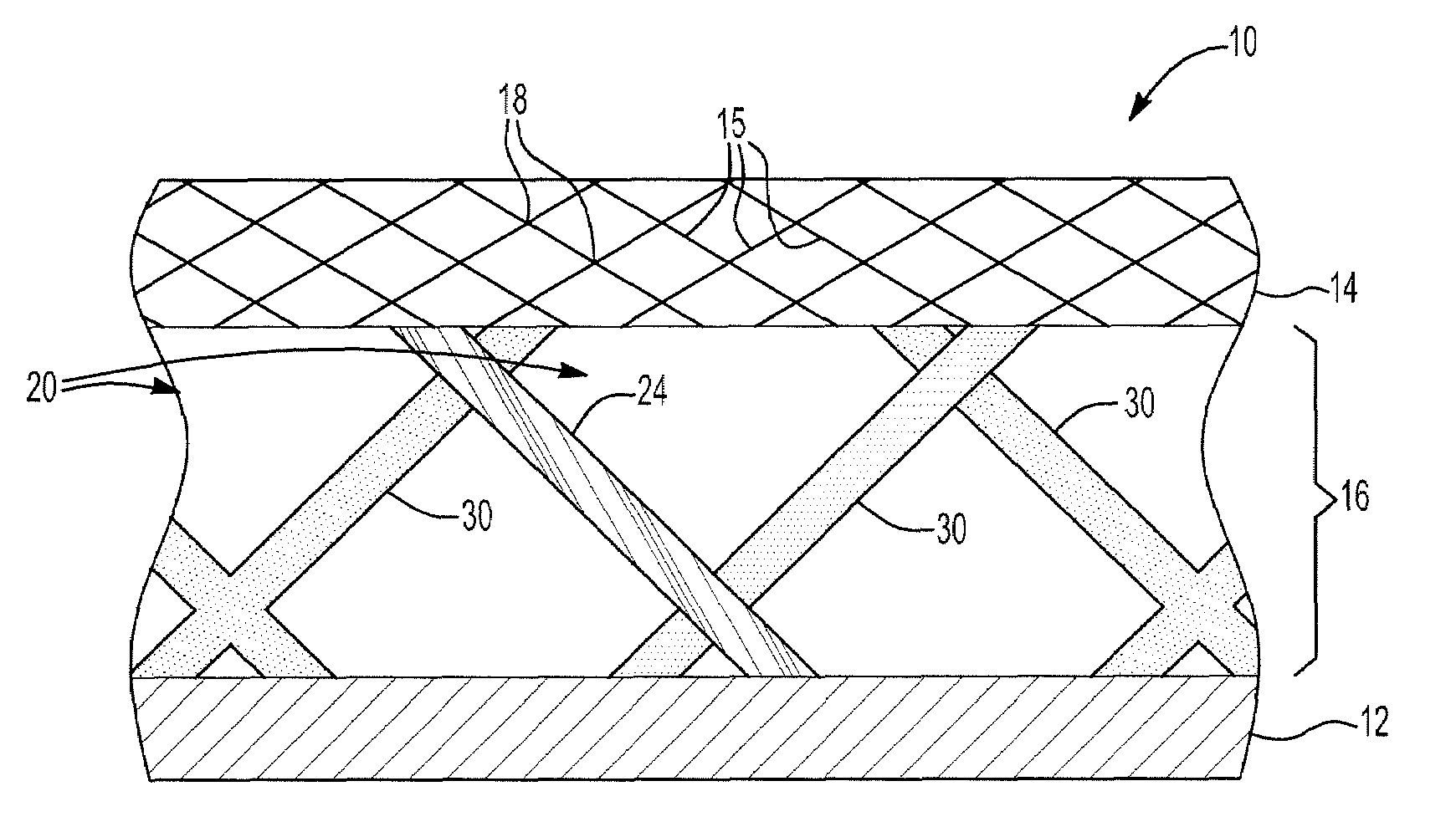
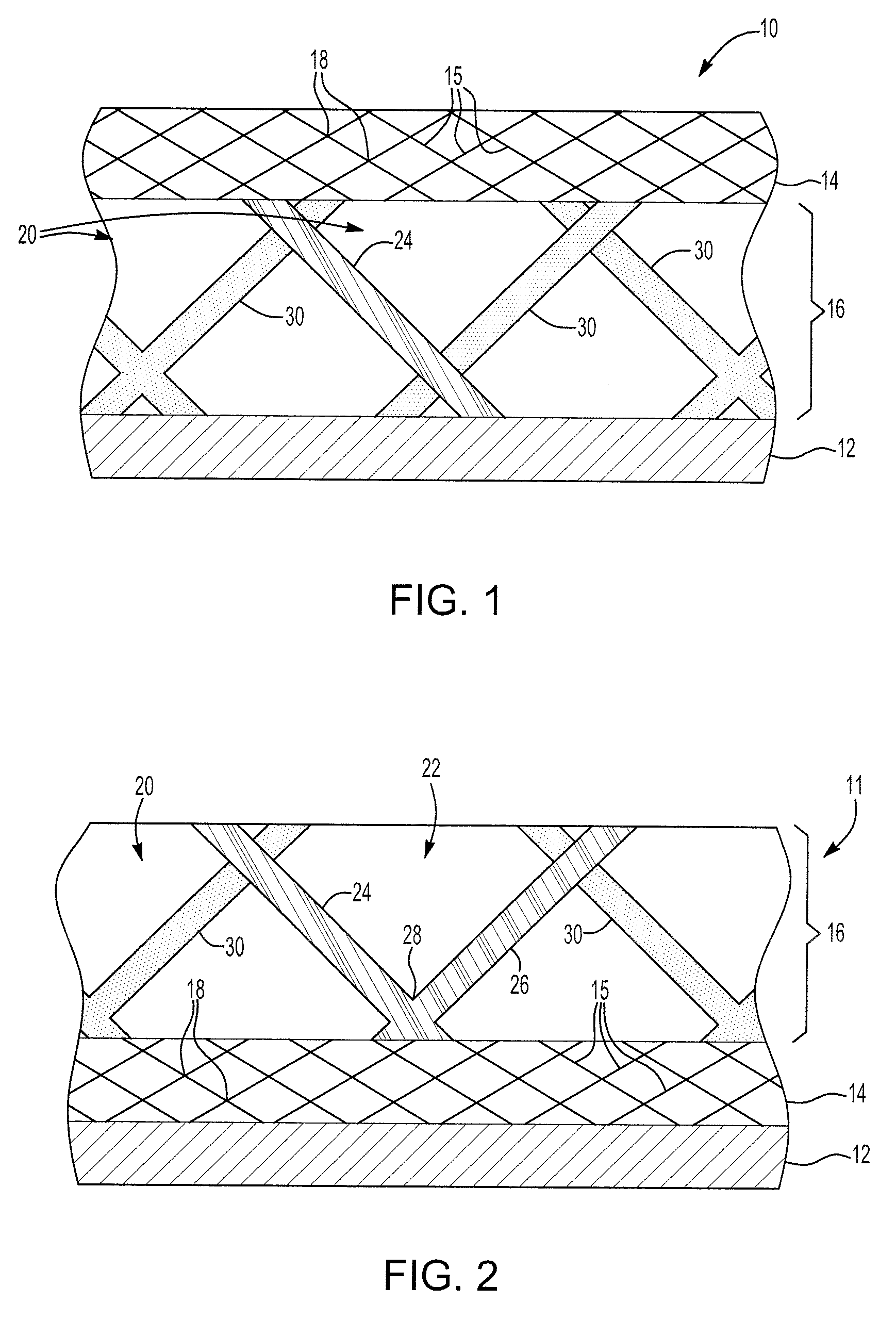
[0021]As shown in FIGS. 1 and 2, a photopolymer based process to fabricate one of a first fuel cell component 10 and a second fuel cell component 11 is provided. The fuel cell components 10, 11 include a substrate 12, at least one diffusion medium layer 14 having a microtruss structure 15, and at least one flow field layer 16. In FIG. 1, the first fuel cell component 10 is shown with the flow field layer 16 disposed between the substrate 12 and the diffusion medium layer 14. In FIG. 2, the second fuel cell component 11 is shown with the diffusion medium layer 14 disposed b...


PUM

PropertyMeasurementUnit
Electrical conductivityaaaaaaaaaa
Flow rateaaaaaaaaaa
Sensitivityaaaaaaaaaa

Abstract

A fuel cell component is provided, including a substrate disposed adjacent at least one radiation-cured flow field layer. The flow field layer is one of disposed between the substrate and a diffusion medium layer, and disposed on the diffusion medium layer opposite the substrate. The flow field layer has at least one of a plurality of reactant flow channels and a plurality of coolant channels for the fuel cell. The fuel cell component may be assembled as part of a repeating unit for a fuel cell stack. A method for fabricating the fuel cell component and the associated repeating unit for the fuel cell is also provided.

Description

FIELD OF THE INVENTION[0001]The present disclosure relates to a fuel cell and more particularly to fuel cell components manufactured by photopolymerization.BACKGROUND OF THE INVENTION[0002]A fuel cell has been proposed as a clean, efficient and environmentally responsible power source for electric vehicles and various other applications. Individual fuel cells can be stacked together in series to form a fuel cell stack for various applications. The fuel cell stack is capable of supplying a quantity of electricity sufficient to power a vehicle. In particular, the fuel cell stack has been identified as a potential alternative for the traditional internal-combustion engine used in modern automobiles.[0003]One type of fuel cell is the polymer electrolyte membrane (PEM) fuel cell. The PEM fuel cell includes three basic components: an electrolyte membrane; and a pair of electrodes, including a cathode and an anode. The electrolyte membrane is sandwiched between the electrodes to form a mem...

Claims


Application Information

Patent Timeline
IPC IPC(8): H01M8/04B05D5/12B05D3/06H01M50/77
CPCH01M8/0232H01M8/0236H01M8/0239Y02E60/50H01M8/0258H01M8/0267H01M2008/1095H01M8/0245B33Y10/00B33Y80/00H01M8/00
Inventor ROCK, JEFFREY A.LAI, YEH-HUNGNEWMAN, KEITH E.FLY, GERALD W.LIU, PINGJACOBSEN, ALAN J.CARTER, WILLIAM B.BREWER, PETER D.
Owner GM GLOBAL TECH OPERATIONS LLC
Why Eureka
Try Eureka