Method and system for diagnosing a machine

a machine and diagnostic technology, applied in the direction of machines/engines, electrical control, instruments, etc., can solve the problems of failure, machine cannot be diagnosed as abnormal and/or abnormal, and it is difficult to make periodic diagnoses, etc., to achieve easy detection, reduce engine output, and reduce engine output

Inactive Publication Date: 2010-06-24
CATEPILLAR SARL
View PDF3 Cites 28 Cited by
  • Summary
  • Abstract
  • Description
  • Claims
  • Application Information

AI Technical Summary

Benefits of technology

[0020]According to the present invention, a decrease in engine output is detected by arranging pieces of frequency distribution information showing a relationship between the size of a power shift pressure and occurrence frequency in time series and by comparing these pieces of frequency distribution information with each other. Therefore, a decrease in engine output can be easily detected by the frequency distribution information regarding the power shift pressure, which can be easily detected, without using threshold values.
[0021]Also, a decrease in engine output is detected by arranging pieces of frequency distribution information showing a relationship between the size of a boost pressure and occurrence frequency in time series and by comparing these pieces of frequency distribution information with each other. Therefore, a decrease in engine output can be easily detected by the frequency distribution information about the boost pressure, which can be easily detected, without using threshold values.
[0022]According to the present invention, a decrease in engine output is detected by arranging pieces of frequency distribution information showing a relationship between the size of engine speed and occurrence frequency in time series and by comparing these pieces of frequency distribution information with each other. Therefore, a decrease in engine output can be easily detected by the frequency distribution information about the engine speed, which can be easily detected, without using threshold values.

Problems solved by technology

Therefore, disadvantageously, much time and effort are required, and it is difficult to make a periodic diagnosis, because operating time and the like are not known until a repair worker visits the site.
Therefore, if the threshold value is not fixed, the machine cannot be diagnosed as being abnormal and / or as being failed.

Method used


Image

  • Method and system for diagnosing a machine
  • Method and system for diagnosing a machine
  • Method and system for diagnosing a machine

Examples


Embodiment Construction

[0037]An embodiment of the present invention will be hereinafter described in detail with reference to FIG. 1 through FIG. 10.

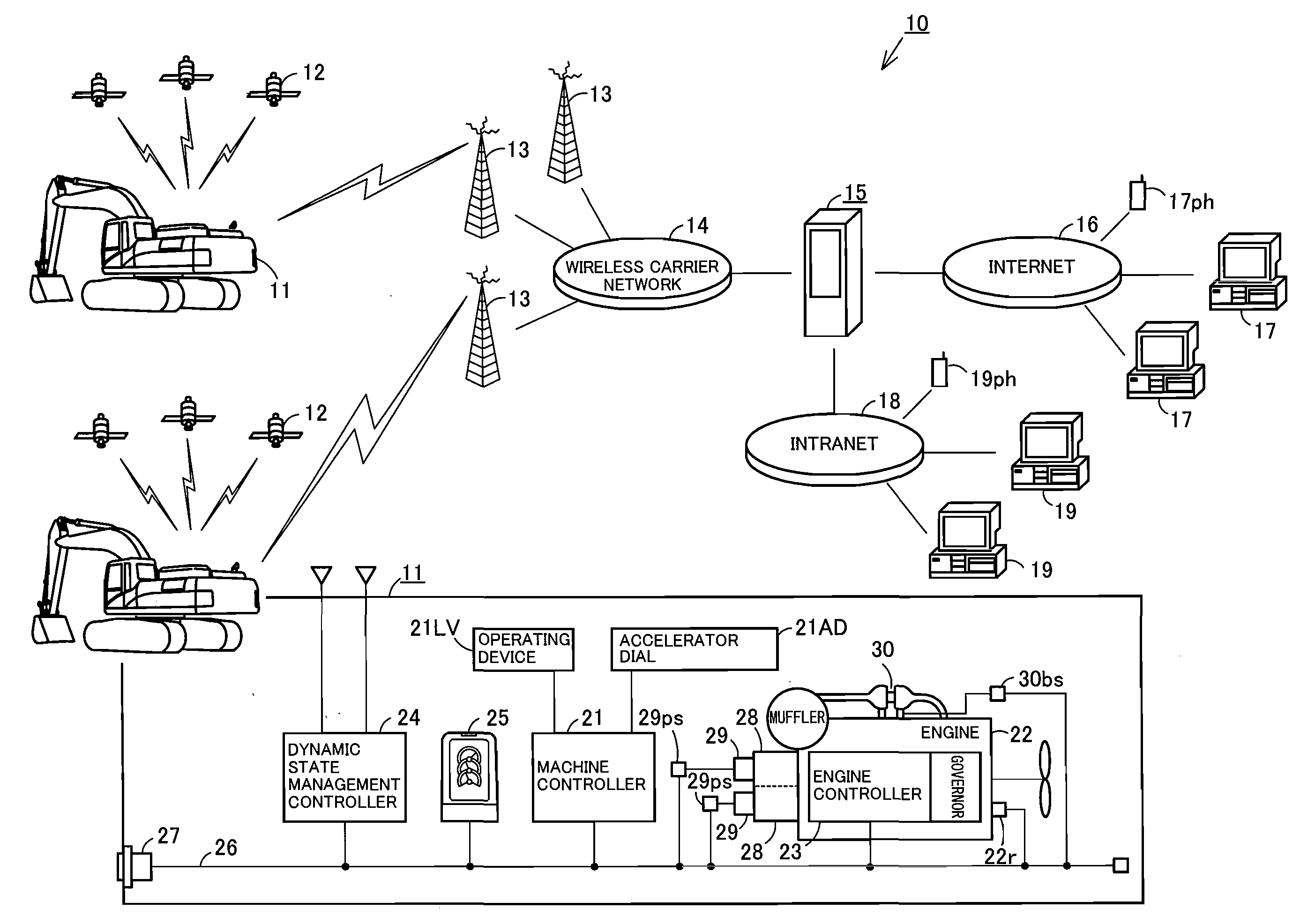
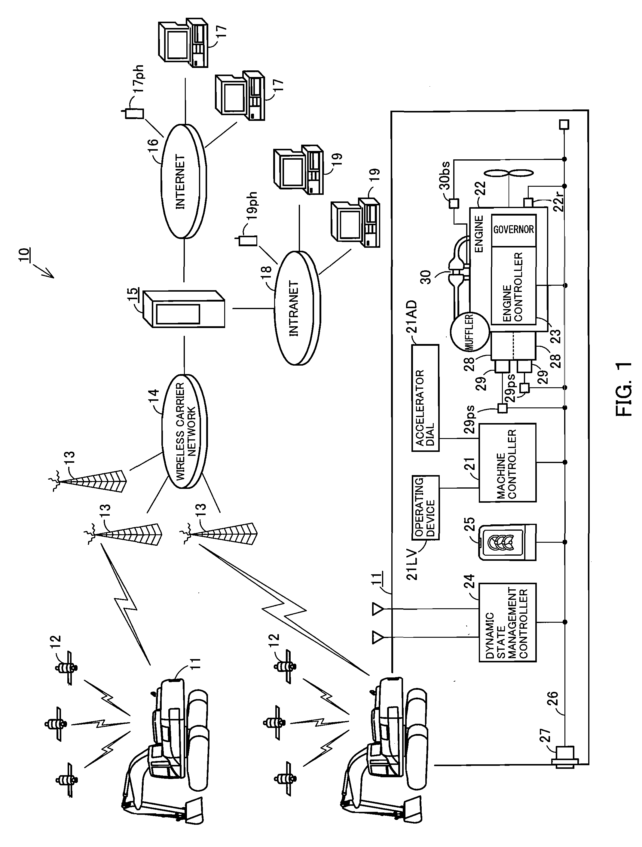
[0038]FIG. 1 is a schematic view of a work-machine remote operation management system 10 that serves as a premise of a machine diagnosing system according to the present invention. The work-machine remote operation management system 10 is used to perform the dynamic state management of a machine body 11 of a work machine at a remote place by means of radio communication. The machine body 11 includes a dynamic state management controller (described later) having an operating data storage function, a radio communication function, and a position-measuring function fulfilled by a global positioning system satellite (hereinafter, the global positioning system is referred to simply as “GPS”) 12. Although the work machine shown in FIG. 1 is a hydraulic shovel, a bulldozer or a loader may be used as the work machine.

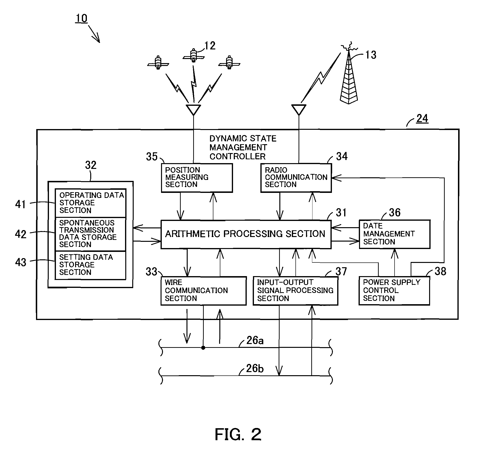
[0039]The dynamic state management controller of th...


PUM


Abstract

A machine diagnosing system is provided which can make an abnormality/failure diagnosis of a machine without using threshold values. It is composed of a dynamic state management controller that creates frequency distribution information showing a relationship between signal intensity related to engine output and occurrence frequency whenever the machine body is operated for a predetermined time, a management section that receives and stores pieces of frequency distribution information, and terminal equipment and each of which detects a decrease in engine output by arranging the pieces of frequency distribution information obtained from the management section in time series and by comparing these pieces of information with each other. A decrease in engine output can be detected, without using threshold values, by comparison between the pieces of frequency distribution information stored concerning the output of the engine, unlike a case in which the abnormality/failure of the machine is determined by comparison with a conventional threshold value or in which the degree of such abnormality is ranked by comparison there.

Description

CROSS-REFERENCE TO PRIOR APPLICATION[0001]This is a U.S. National Phase Application under 35 U.S.C. §371 of International Patent Application No. PCT / JP2007 / 062743 filed Jun. 26, 2007, which claims the benefit of Japanese Patent Application No. 2007-034034 filed Feb. 14, 2007, both of which are incorporated by reference herein. The International Application has not yet been published.TECHNICAL FIELD[0002]The present invention relates to a method and a system for diagnosing a machine by use of a dynamic state management controller having an operating data storage function and a radio communication function.BACKGROUND ART[0003]As shown in FIG. 11, a machine 1, such as a hydraulic shovel, includes a machine controller 2 that controls the operation of the machine 1, an engine controller 4 that controls the fuel injection of an engine 3 mounted on the machine 1, and a monitor 5 that is an output device used also as an input device operated by an operator working in a cab of the machine 1....

Claims


Application Information

Patent Timeline
Patent Type & Authority Applications(United States)
IPC IPC(8): G01M15/02E02F9/26
CPCE02F9/2025E02F9/26F02D29/00Y02T10/40F02D41/021F02D41/22F02D41/0007E02F9/267
Inventor YAMADA, HIDEOSAKAI, MAKOTOMATSUFUJI, KAZUMOTOTANAKA, JUN
Owner CATEPILLAR SARL
Why Eureka
Try Eureka