Vehicle operation support system and navigation apparatus

a technology of vehicle operation and support system, which is applied in the direction of navigation instruments, process and machine control, etc., can solve the problems of delay in the operation of vehicle drive control, delay in the operation of acquiring information about the exit road, and interruption of other tasks, so as to improve the real-time response and avoid the influence of delay in communication

Inactive Publication Date: 2010-06-24
HITACHI AUTOMOTIVE SYST LTD +1
View PDF6 Cites 50 Cited by
  • Summary
  • Abstract
  • Description
  • Claims
  • Application Information

AI Technical Summary

Benefits of technology

[0006]In view of the foregoing, it is desirable to provide a vehicle operation support system and a navigation apparatus which are capable of allowing a drive control device to operate with improved real-time response and reliability with no influence of delay in communication.

Problems solved by technology

This may cause a delay in start of operation of the drive control device.
Accordingly, applications, such as of map matching, and lane selection estimation, which cooperate with an application of vehicle drive control, may be delayed by interruption of other tasks.
In the case of the exit road of the expressway described above, when startup and operation of the locator is delayed by interruption of other applications such as of the HMI, a telephone, and intercommunications, the delay may cause a delay in the operation of acquiring information about the exit road which is performed after startup and operation of the locator.
This problem may be significant, when the vehicle operation support system is configured with a CAN (Controller Area Network) network as a multiplex communication network.
In this way, in the vehicle operation support system disclosed in Japanese Patent Application Publication No. 2001-289654, when transmission of road information is delayed, the delay may cause a delay in start of operation of the drive control device, because the operation of the drive control device is performed with reference to the information acquired by map matching operation.

Method used


Image

  • Vehicle operation support system and navigation apparatus
  • Vehicle operation support system and navigation apparatus
  • Vehicle operation support system and navigation apparatus

Examples


first embodiment

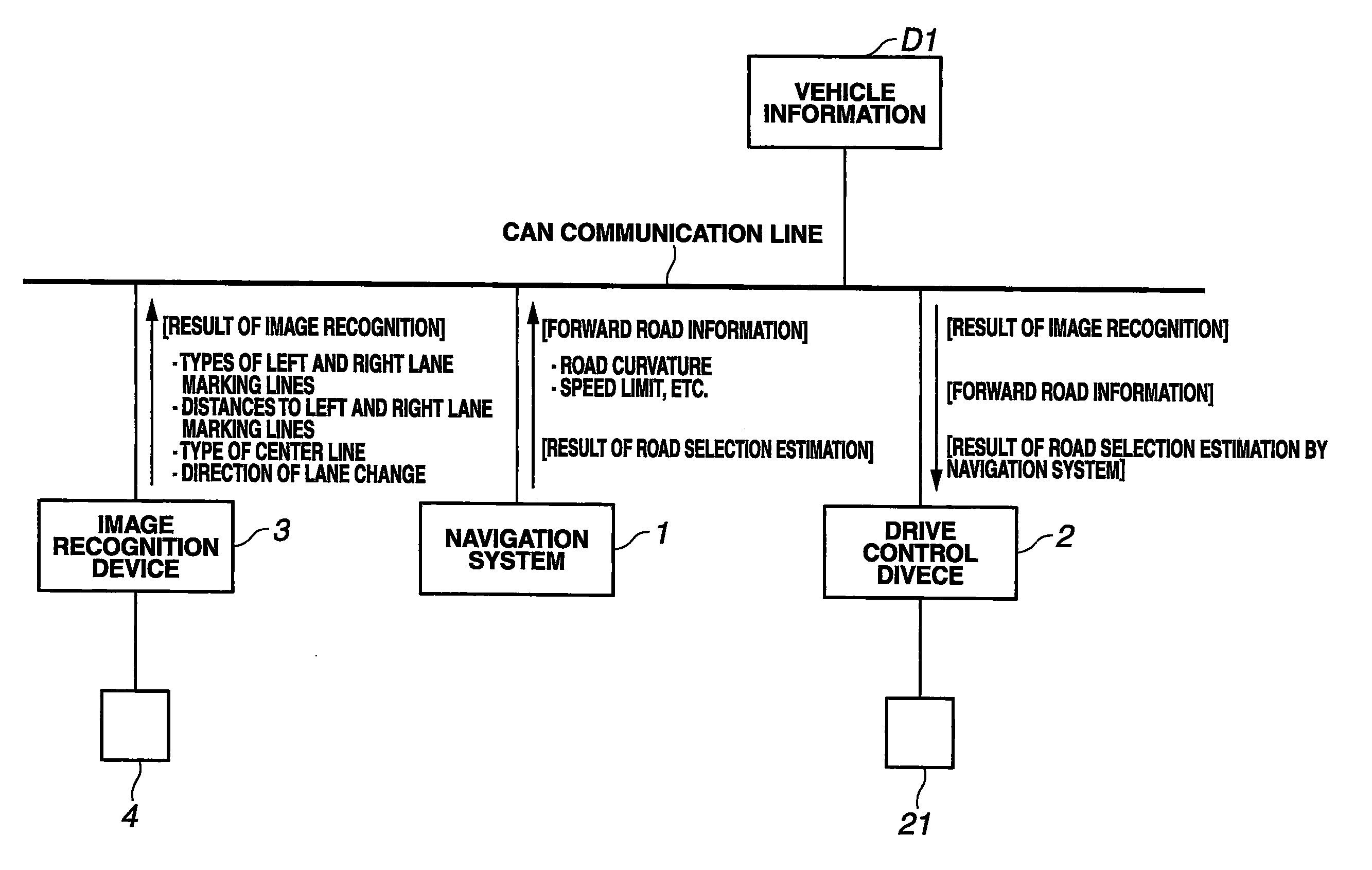
[0052]The following describes a vehicle operation support system according to a first embodiment of the present invention with reference to FIGS. 1 to 25. FIG. 1 schematically shows configuration of the vehicle operation support system.

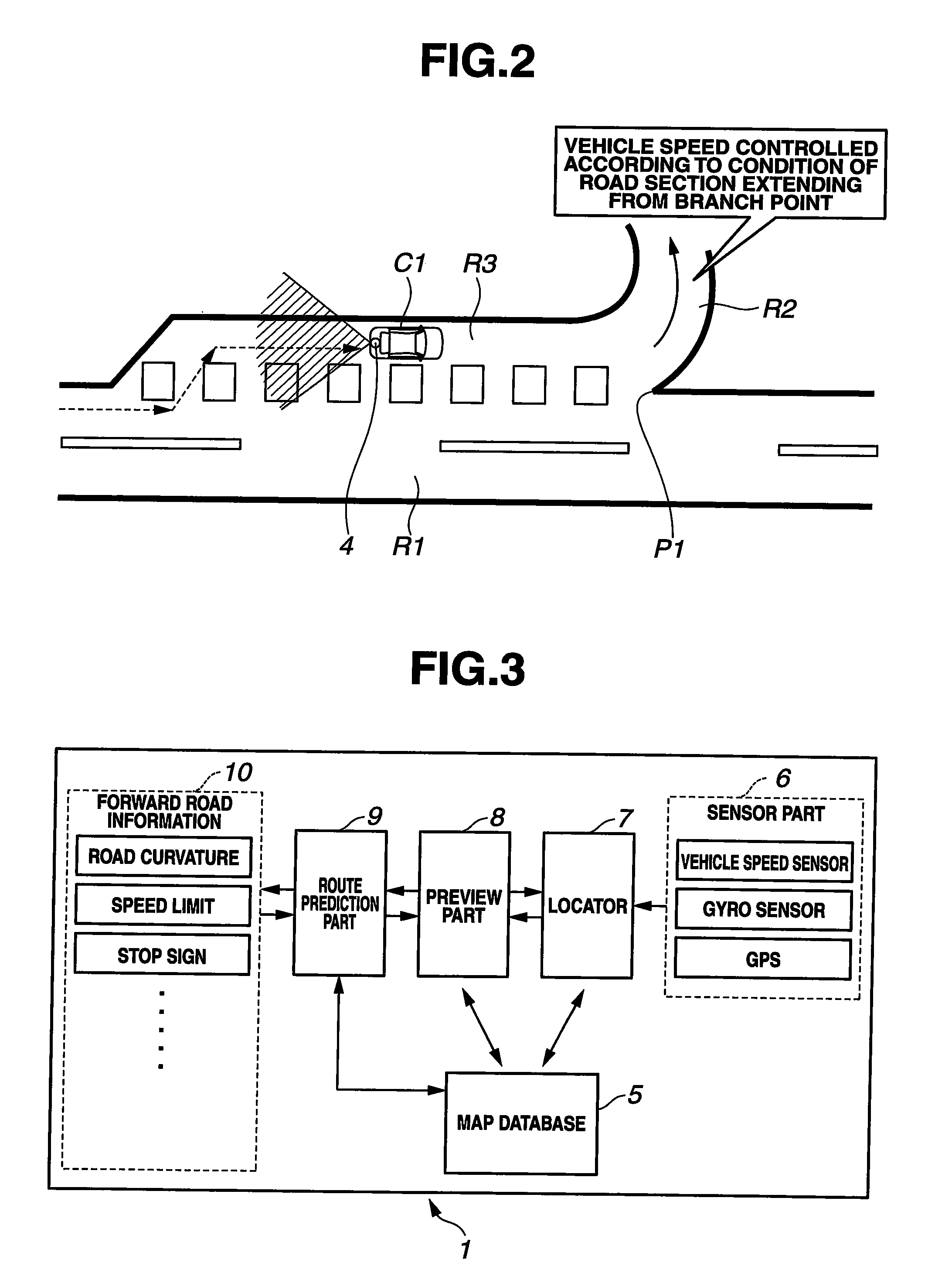
[0053]The vehicle operation support system is adapted, for example, to a section of an expressway as shown in FIG. 2 in which an exit road as a branch road R2 branches from a through traffic road (or main road) R1 through a deceleration lane R3. As described in detail below, the vehicle operation support system is configured to: suitably determine which of the through traffic road R1 and branch road R2 a host vehicle C1 is going to travel in, before host vehicle C1 reaches a branch point P1; and perform engine control and / or brake control with a drive control device, with reference to information, such as curvature data, speed limit data, etc., about the branch road R2, so that the host vehicle C1 can continue smoothly traveling while suitably deceler...

second embodiment

[0125]The following describes a vehicle operation support system according to a second embodiment of the present invention with reference to FIGS. 26 to 36. As described above, in the first embodiment, the information that the branch road R2 as well as deceleration lane R3 branches from through traffic road R1 at branch point P1, and that the branch road R2 branches to the left side, is obtained with reference to the link type of branch road R2 which is stored in map database 5. The vehicle operation support system according to the second embodiment is configured to deal with a branch section where branch road R2 is not discriminated from through traffic road R1 in map data, although as shown in FIG. 26, the branch section has substantially the same shape as the section shown in FIG. 11. Similar to the branch section shown in FIG. 26, at a junction section in an expressway as shown in FIG. 27 where a road branches into two branch roads, the link of each branch road is a connection r...

third embodiment

[0141]The following describes a vehicle operation support system according to a third embodiment of the present invention with reference to FIGS. 37 to 39. FIGS. 37 to 39 show a procedure of branch point control to be performed by the vehicle operation support system according to the third embodiment. The third embodiment differs from the first embodiment in provision of Steps S66 to S70 shown in FIG. 37 instead of Step S6 to S9 shown in FIG. 8.

[0142]The following describes Steps S66 to S70 in FIG. 37. At Step S66, the vehicle operation support system determines whether the branch road forward road information is neither acquired nor sent. When the answer to Step S66 is affirmative (YES), then the procedure proceeds to Step S67 at which in response to recognition that the host vehicle C1 has reached the preview starting point P4, navigation system 1 obtains by collection or calculation the branch road forward road information which is information about a section of branch road R2 ex...


PUM


Abstract

A vehicle operation support system includes a navigation device, and a drive control device. The navigation device includes: part for storing road information including branch point information; and part for acquiring road curvature information with reference to the road information, and providing the drive control device with the road curvature information, before a vehicle reaches the branch point. The road curvature information includes information about curvature of first and second road sections extending forward from a branch point. The drive control device estimates entrance of the vehicle into one of the first and second road sections as a selected road section, and controls a driving state of the vehicle by operating an actuator with reference to information about curvature of the selected road section, in response to estimation of entrance of the vehicle into the selected road section.

Description

BACKGROUND OF THE INVENTION[0001]The present invention relates to vehicle operation support systems and navigation apparatuses for supporting vehicle operation with reference to road information.[0002]Japanese Patent Application Publication No. 2001-289654 corresponding to U.S. Pat. No. 6,385,536 discloses a vehicle operation support system with a navigation device for a vehicle, which includes a section for locating the vehicle, a section for storing road information, a section for acquiring images of roads, a section for recognizing lane markers, a section for extracting characteristics of branch points, and a section for determination about branch points. For example, when the vehicle is traveling in an expressway and approaching a branch point where an exit road branches from a through traffic road, the vehicle operation support system: determines with reference to a result of recognition of lane markers which direction the vehicle is traveling in or which lane the vehicle is tr...

Claims


Application Information

Patent Timeline
Patent Type & Authority Applications(United States)
IPC IPC(8): G06F7/00G01C21/26B60T7/12B60W30/00B60W30/14B60W50/06G01C21/00G01C21/30G08G1/16
CPCB60W10/06B60W10/184B60W30/18009B60W2550/141B60W40/072B60W2550/22B60W2550/402B60W2720/10G01C21/26B60W2550/143B60W2552/05B60W2552/20B60W2555/60B60W2556/50B60W2552/30B60W50/0097B60W30/18145
Inventor NARA, NORIKAZUUEYAMA, MIKIOSAKATA, MASAOITO, SATOSHINAKAMURA, JUNYA
Owner HITACHI AUTOMOTIVE SYST LTD
Why Eureka
Try Eureka