Multi channel data transfer device

a data transfer device and multi-channel technology, applied in the direction of electric digital data processing, program control using stored programs, instruments, etc., can solve the problems of long time to set a plurality of control registers and system performance degradation, so as to reduce the number of control registers and reduce the load of control

Inactive Publication Date: 2010-06-24
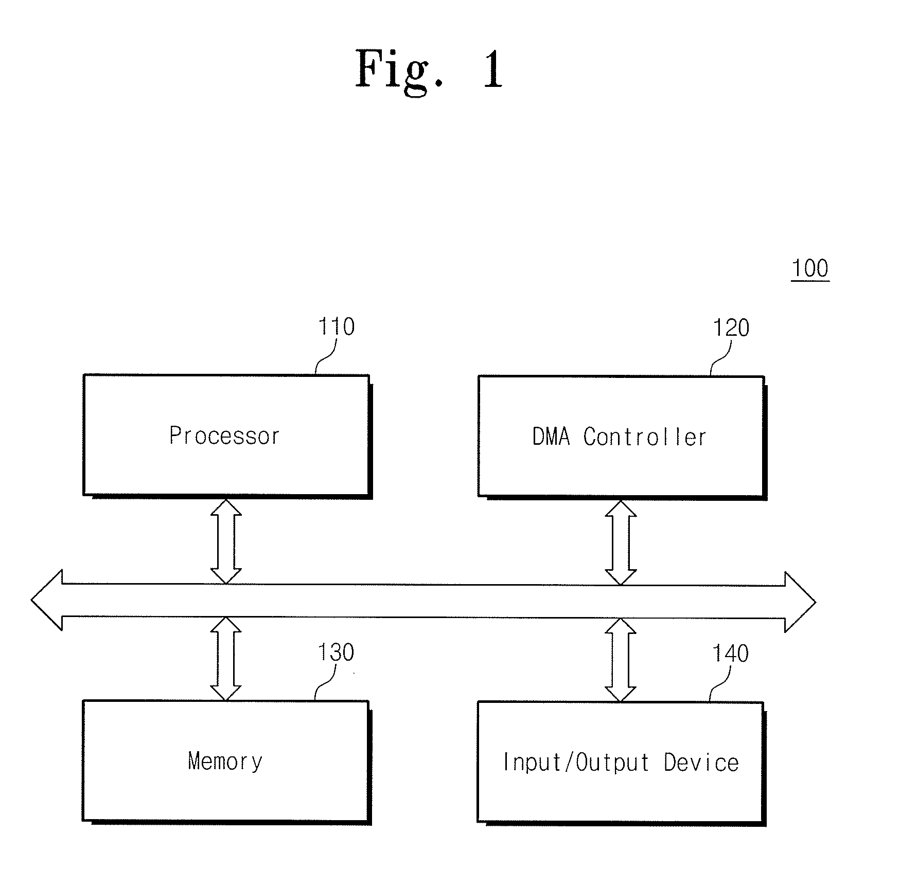
ELECTRONICS & TELECOMM RES INST
View PDF10 Cites 11 Cited by
  • Summary
  • Abstract
  • Description
  • Claims
  • Application Information

AI Technical Summary

Benefits of technology

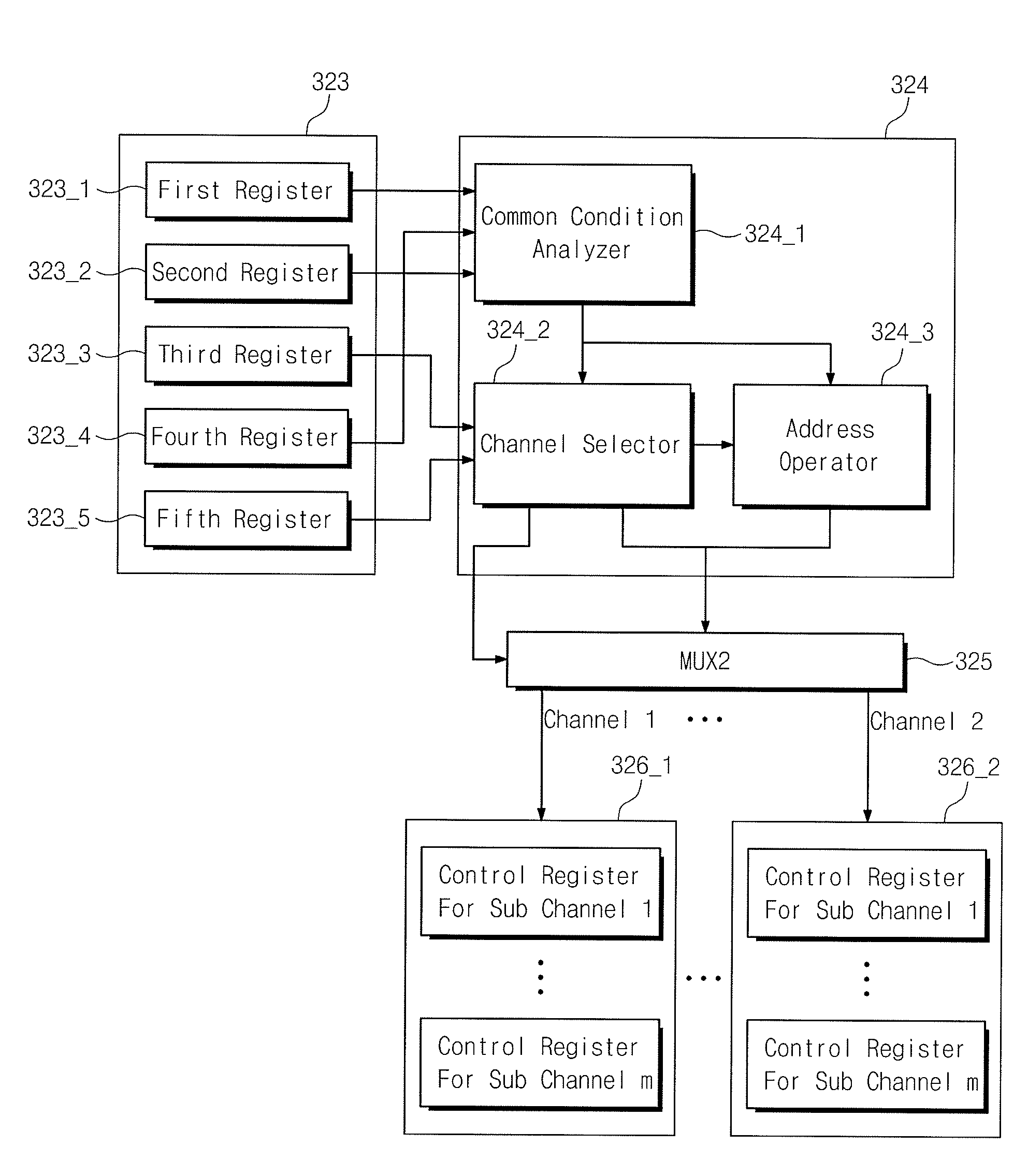
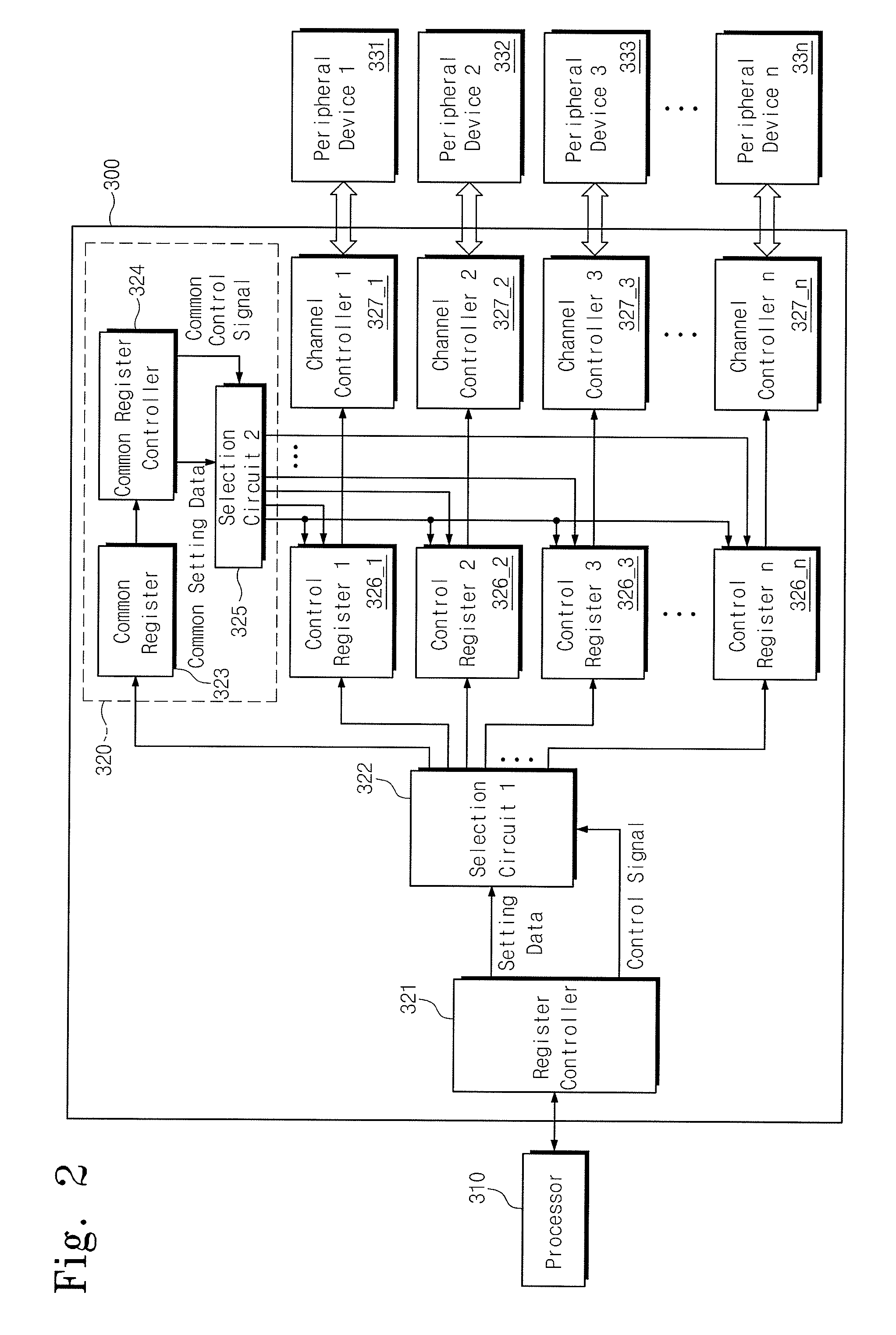
[0007]The present invention provides a multi channel data transfer device capable of reducing a control load caused by a processor and improving efficiency of a system bus by minimizing register setting repetition accompanied by a multi channel transfer.

Problems solved by technology

Since it takes a relatively long time to set a plurality of control registers, system performance is deteriorated.

Method used


Image

  • Multi channel data transfer device
  • Multi channel data transfer device
  • Multi channel data transfer device

Examples


Embodiment Construction

[0019]Embodiments will be described below in more detail with reference to the accompanying drawings. The embodiments may, however, be embodied in different forms and should not be construed as limited to the embodiments set forth herein. Rather, these embodiments are provided so that this disclosure will be thorough and complete, and will fully convey the scope of the embodiments to those skilled in the art.

[0020]It should be construed that foregoing general illustrations and following detailed descriptions are exemplified and an additional explanation of claimed inventions is provided. Reference numerals are indicated in detail in preferred embodiments, and their examples are represented in reference drawings. In every possible case, like reference numerals are used for referring to the same or similar elements in the description and drawings.

[0021]Below, a multi channel data transfer device is used as one example for illustrating characteristics and functions of the embodiments. ...


PUM


Abstract

Provided is a multi channel data transfer device. The multi channel data transfer device includes: a plurality of channel control unit connected to a plurality of peripheral devices, respectively; a plurality of control registers storing setting data for controlling an operation of each of the plurality of channel controllers; and a common register controller delivering common setting data to all or part of the plurality of control registers, the common setting data being applied in common to all or part of the plurality of channel controllers.

Description

CROSS-REFERENCE TO RELATED APPLICATIONS[0001]This U.S. non-provisional patent application claims priority under 35 U.S.C. §119 of Korean Patent Application No. 10-2008-0131186, filed on Dec. 22, 2008, the entire contents of which are hereby incorporated by reference.BACKGROUND OF THE INVENTION[0002]The present invention disclosed herein relates to a multi channel data transfer device transmitting data through a plurality of channels.[0003]A multimedia processor processes a large capacity of data. The performance of the multimedia processor depends on a data transfer speed between a processing module and a memory. In order to improve a data transfer speed, a direct memory access (DMA) technique is used.[0004]In relation to the DMA technique, a processor is not responsible for data transfer during the transferring of data. Instead of that, data are directly transferred between a peripheral device and a memory using an additional data transfer device. That is, according to the DMA tech...

Claims


Application Information

Patent Timeline
Patent Type & Authority Applications(United States)
IPC IPC(8): G06F13/28
CPCG06F13/122G06F9/06G06F13/14G06F13/38
Inventor SUK, JUNG-HEECHUN, IK-JAEYANG, YIL-SUKHEO, SE-WANROH, TAE-MOONKIM, JONG-DAE
Owner ELECTRONICS & TELECOMM RES INST
Why Eureka
Try Eureka