
Composite core for an electrical cable

a technology of composite core and electrical cable, which is applied in the direction of insulated conductors, power cables, cables, etc., can solve the problems of single fiber/thermoplastic composite core failing to one fiber/thermoplastic system does not have the physical characteristics to effectively transfer load, and the composite core comprising glass fiber and thermoplastic resin does not meet the operating temperature requirements for increased ampacity

Inactive Publication Date: 2010-07-01
CTC GLOBAL CORP
View PDF30 Cites 37 Cited by
  • Summary
  • Abstract
  • Description
  • Claims
  • Application Information

AI Technical Summary

Benefits of technology

The present invention is about an improved electrical cable design that uses a composite core made of fiber reinforcements and a matrix. This composite core is surrounded by aluminum conductor wires. The cable is designed to have increased ampacity, meaning it can carry more electrical current, and can operate at higher temperatures without sagging. The invention solves the problem of traditional cables being limited by the physical characteristics of the components, which limit their load bearing ability. The invention also allows for processing the composite cores during manufacturing, allowing for faster processing speeds and the ability to tune the core for increased load capacity. The ACCC cable design can increase the load carrying capacity of transmission cables without requiring significant modifications to the existing infrastructure.

Problems solved by technology

The single fiber / thermoplastic composite core failed in these objectives.
A one fiber / thermoplastic system does not have the required physical characteristics to effectively transfer load while keeping the cable from sagging.
Secondly, a composite core comprising glass fiber and thermoplastic resin does not meet the operating temperatures required for increased ampacity, namely, between 90° C. and 240° C., or higher.
Physical properties of thermoplastic composite cores are further limited by processing methods.
Previous processing methods cannot achieve a high fiber to resin ratio by volume or weight.
These processes do not allow for creation of a fiber rich core that will achieve the strength required for electrical cables.
Moreover, the processing speed of previous processing methods is limited by inherent characteristics of the process itself.
The longer dies create increased friction between the composite and the die slowing processing time.
With thousands of miles of cables needed, these slow processing speeds fail to meet the need in a financially acceptable manner.

Method used


Image

  • Composite core for an electrical cable
  • Composite core for an electrical cable
  • Composite core for an electrical cable

Examples


Embodiment Construction

[0025]The present invention will now be described more fully hereinafter with reference to the accompanying drawings, in which exemplary embodiments of the invention are shown. This invention may, however, be embodied in many different forms and should not be construed as limited to the embodiments set forth herein; rather, these embodiments are provided so that the disclosure will fully convey the scope of the invention to those skilled in the art.

[0026]An ACCC Reinforced Cable

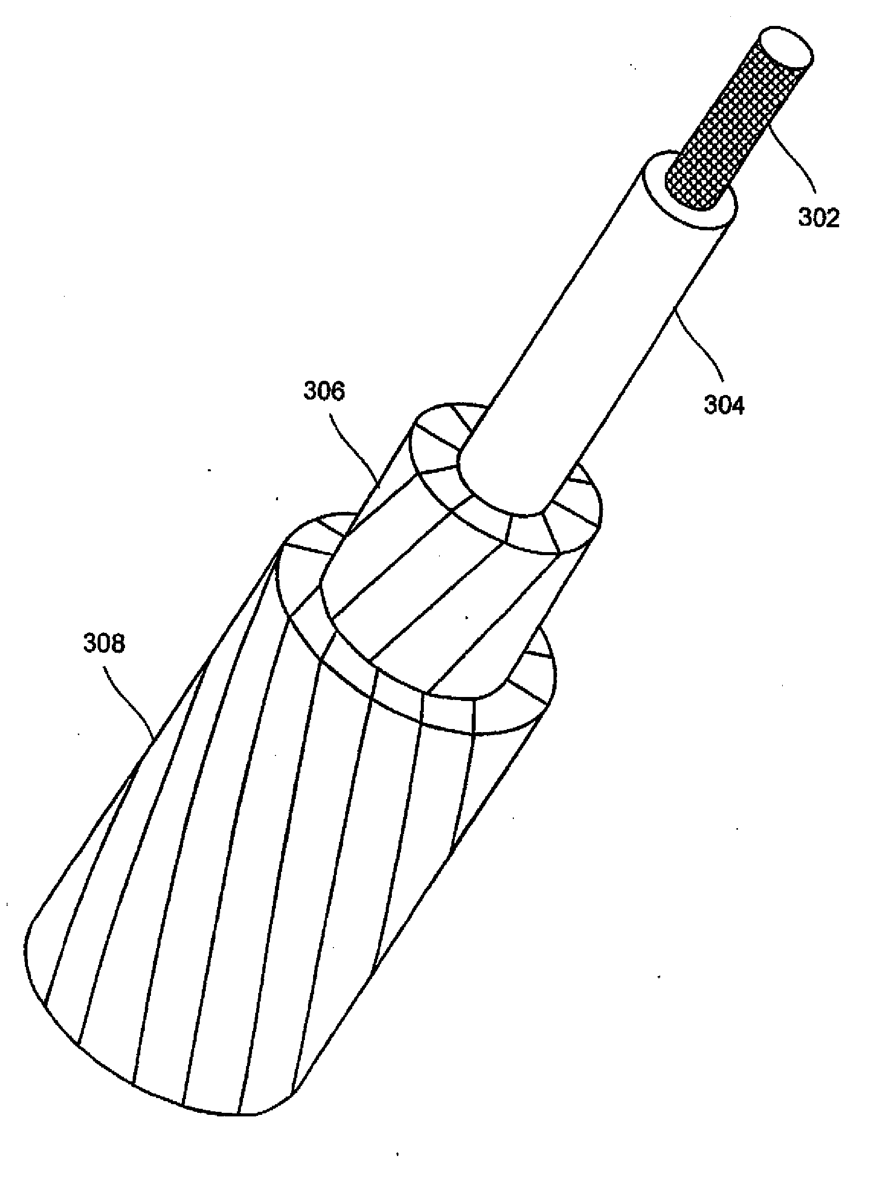
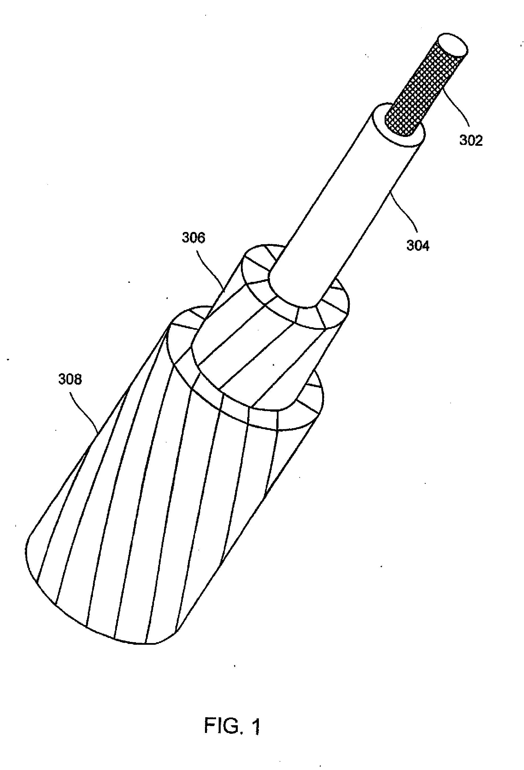
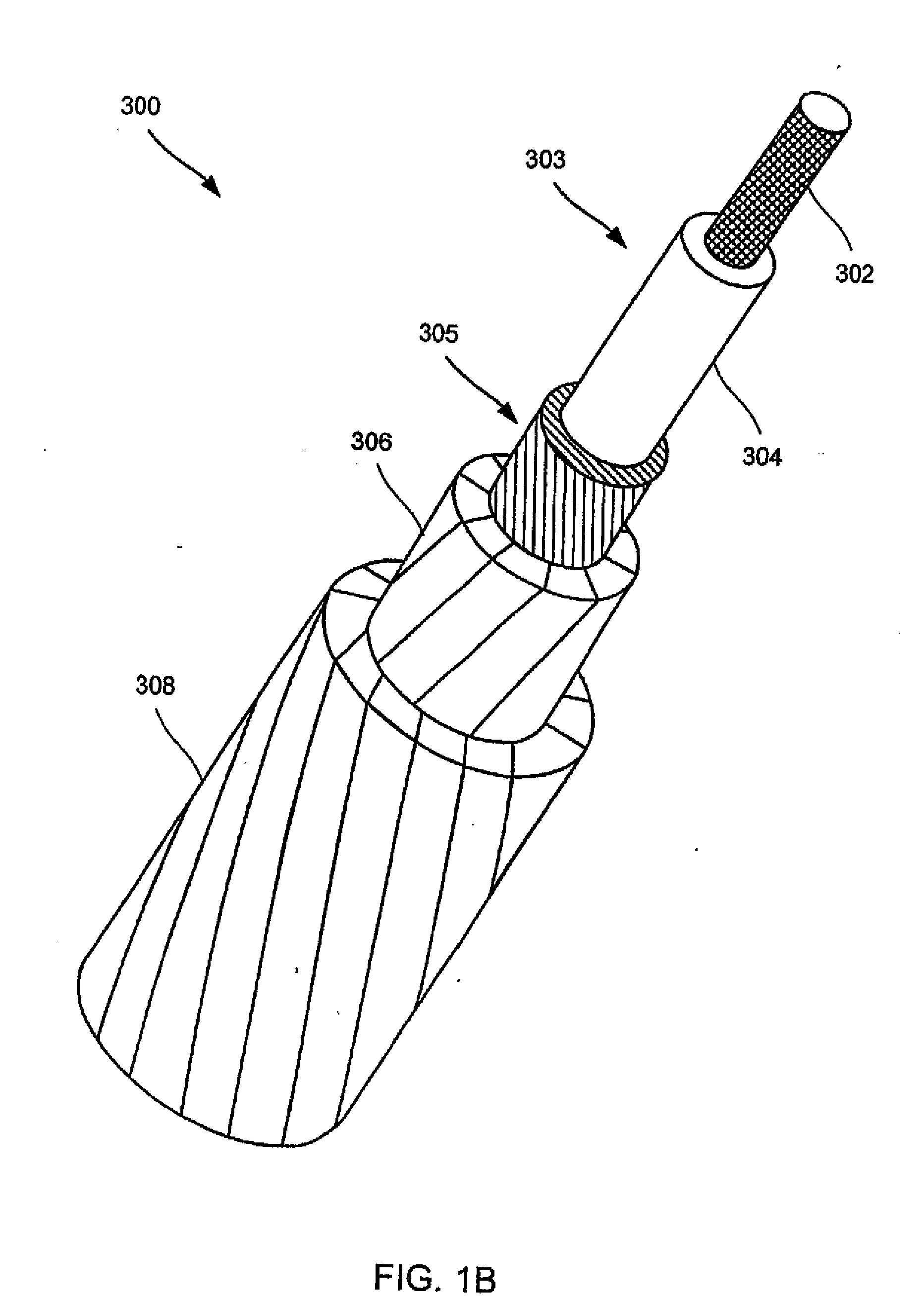
[0027]The present invention relates to a reinforced composite core member, wherein said member further comprises an external surface coating. In one embodiment, the composite core comprises a composite material made from a plurality of fiber reinforcements from one or more fiber types embedded in a matrix. A further embodiment of the invention uses the composite core in an aluminum conductor composite core reinforced (ACCC) cable. These ACCC cables can provide for electrical power distribution wherein electri...


PUM

PropertyMeasurementUnit
temperaturesaaaaaaaaaa
speedsaaaaaaaaaa

Abstract

This invention relates to an aluminum conductor composite core reinforced cable (ACCC) and method of manufacture. An ACCC cable (300) has a composite core and at least one layer of aluminum conductor (306). The composite core (303) comprises a plurality of fibers from at least one fiber type in one or more matrix materials. According to the invention, unique processing techniques such a B-Staging and / or film-coating techniques can be used to increase production rates from a few feet per minute to sixty or more feet per minute.

Description

CROSS-REFERENCE TO RELATED APPLICATIONS[0001]This application claims priority as a divisional application of U.S. patent application Ser. No. 10 / 595,459 filed on Jan. 26, 2007, which is an application under 35 USC §371 of U.S. PCT Application No. PCT / US04 / 035201 filed on Oct. 22, 2004, which claims priority to U.S. patent application Ser. No. 10 / 692,304, filed Oct. 23, 2003, now U.S. Pat. No. 7,060,326 and to U.S. patent application Ser. No. 10 / 691,447, filed Oct. 22, 2003, now U.S. Pat. No. 7,211,319. Each of the foregoing applications is incorporated herein by reference in its entirety.TECHNICAL FIELD[0002]The present invention relates to an aluminum conductor composite core (ACCC) reinforced cable and method of manufacture. More particularly, the present invention relates to a cable for providing electrical power having a composite core, formed by fiber reinforcements and a matrix, surrounded by aluminum conductor wires capable of carrying increased ampacity and operating at elev...

Claims


Application Information

Patent Timeline
Patent Type & Authority Applications(United States)
IPC IPC(8): H01B5/10H01B9/00H01B17/14D02G3/36D02G3/02B32B5/12D03D25/00D04C1/00B05D1/18B05D3/02B32B27/04B65HD04H3/08
CPCB29C70/52B29L2031/3462B32B1/00B32B15/02B32B15/08Y10T428/2918B32B27/04H01B5/105Y10T442/30Y10T428/2933Y10T428/2936B32B15/20B29C70/528B82Y30/00B32B2305/08B32B2307/54B32B27/08B32B2457/00
Inventor HIEL, CLEMENTBRYANT, DAVIDKORZENIOWSKI, GEORGE
Owner CTC GLOBAL CORP
Learn More