Fan drive

a fan drive and fan body technology, applied in the direction of fluid couplings, couplings, machines/engines, etc., can solve the problems of roller bearings being subjected to intense loads, blockage of clutches, and insufficient cooling effect at higher capacities, so as to improve the cooling effect

Active Publication Date: 2010-07-01
MAHLE INT GMBH
View PDF6 Cites 12 Cited by
  • Summary
  • Abstract
  • Description
  • Claims
  • Application Information

AI Technical Summary

Benefits of technology

[0008]It is an object of the invention to improve the cooling and especially the cooling of a fluid friction clutch in a fan drive of the kin

Problems solved by technology

This cooling effect is not adequate at higher capacities, especially, at higher drive rpms.
The danger here is presented that the silicone oil will overheat and this can then lead to the silicone oil losing its transfer capability which can lead to a blockage

Method used


Image

  • Fan drive
  • Fan drive
  • Fan drive

Examples


Embodiment Construction

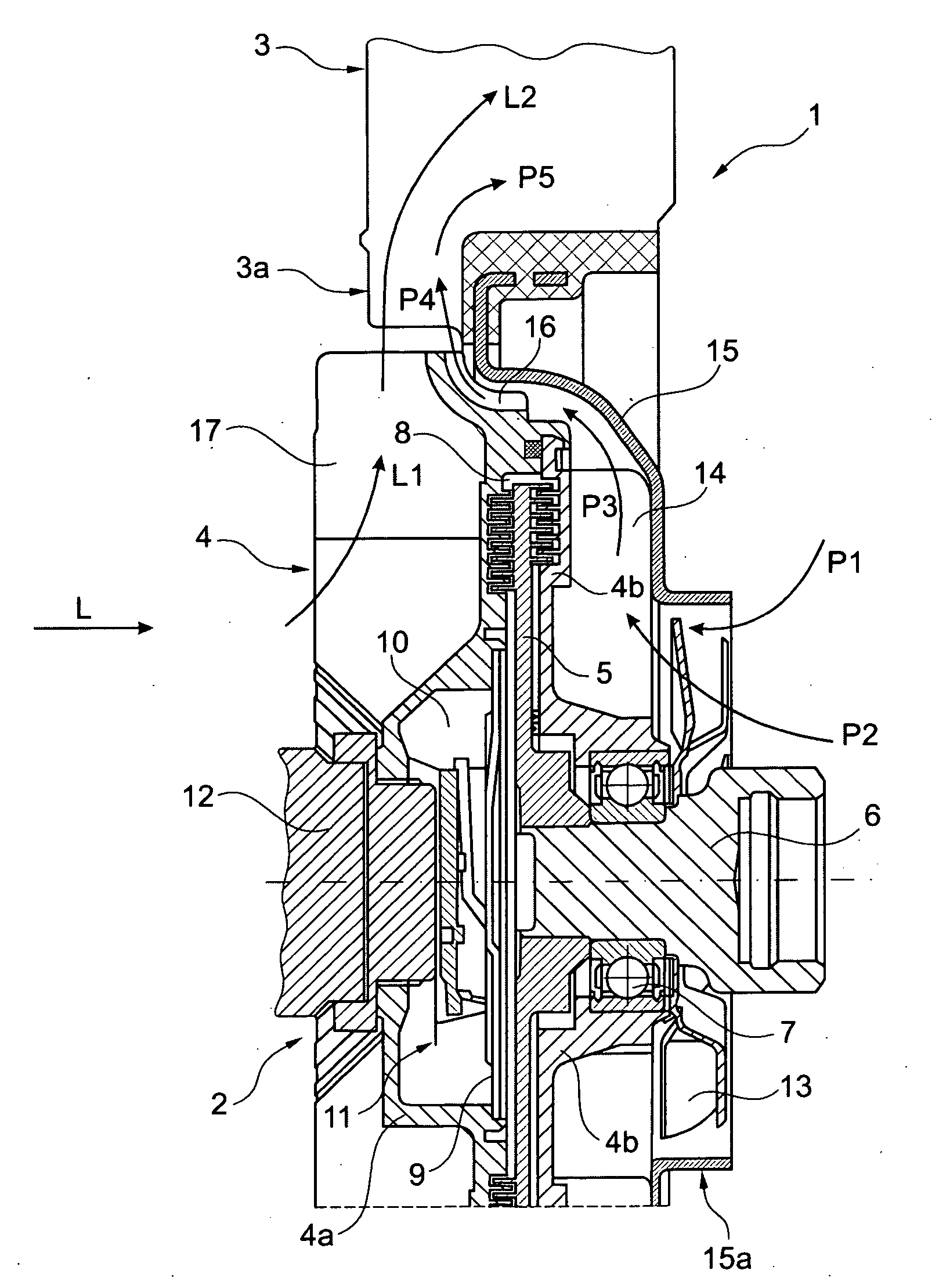
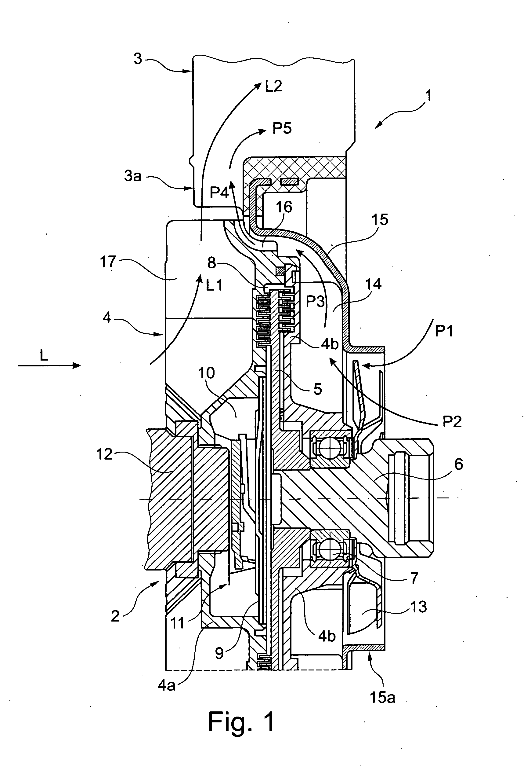
[0021]FIG. 1 shows a section view of a fan drive 1 according to the invention. The fan drive includes a fluid friction clutch 2 and a fan 3 configured as an axial fan. The fan 3 is driven by the fluid friction clutch 2.

[0022]The fluid friction clutch 2 includes a housing 4 which is configured of a front-end housing part 4a and a rear-end housing part 4b. The terms forward or front-end housing part and rear-end housing part should be viewed with reference to the air flow direction shown by arrow L in FIG. 1. In the following, the fluid friction clutch 2 is also referred to as just clutch 2 and includes a drive disc 5 which is attached to a drive shaft 6 so as to rotate therewith and is driven thereby. The housing 4 is rotatably journalled relative to the drive shaft 6 via a bearing configured as a roller bearing 7. The housing 4 and the drive disc 5 conjointly define a labyrinth-like work chamber 8 which is configured by a plurality of gaps fillable with a shear liquid, especially, s...


PUM


Abstract

A fan drive (1) includes a drive shaft (6), a fluid friction clutch (2) as well as a fan (3). The fluid friction clutch (2) includes a drive disc (5) as well as a housing (4) having a front-end housing part (4a) and a rear-end housing part (4b). The housing (4) is journalled on a drive shaft (6) via at least one bearing (7). Air flows against the fluid friction clutch (2) and the fan (3) in flow direction (L). An air-conveying unit (13) is mounted in flow direction (L) behind the fluid friction clutch (2). The fan drive is especially for a motor vehicle.

Description

CROSS REFERENCE TO RELATED APPLICATION[0001]This application claims priority of German patent application no. 10 2008 063 702.5, filed Dec. 19, 2008, the entire content of which is incorporated herein by reference.FIELD OF THE INVENTION[0002]The invention relates to a fan drive and especially a fan drive for a motor vehicle.BACKGROUND OF THE INVENTION[0003]Fan drives are utilized for cooling the internal combustion engine of a motor vehicle and are, as a rule, mounted in the engine compartment of the motor vehicle behind a heat-transfer unit or an assembly unit of several heat-transfer units, for example, a coolant radiator, a charge-air cooler and / or a coolant condenser.[0004]It is known to not drive the fan directly by the engine but, instead, by a controlled clutch, for example, a fluid friction clutch. Because of the control, an efficient and energy-saving cooling is achieved wherein the fan is only switched on when cooling is needed and, if needed, at different rpms adapted to ...

Claims


Application Information

Patent Timeline
IPC IPC(8): F16D31/00
CPCF01P5/06F01P7/042F04D25/022F16D35/02
Inventor SIXT, EBERHARDKLEIN, KURTJACOBI, MICHAEL
Owner MAHLE INT GMBH
Why Eureka
Try Eureka