Resilient structure

Inactive Publication Date: 2010-07-01
HUANG TAN CHENG
View PDF11 Cites 1 Cited by
  • Summary
  • Abstract
  • Description
  • Claims
  • Application Information

AI Technical Summary

Benefits of technology

[0015]A second advantage of the present invention is that the size and weight of the present invention are reduced compare to that of the conventional resilient structures. Compare to the conventional rubber resilient unit, the compression stroke of the present invention is significantly increased, and the compression rate relative to a length of the resilient structure is also increased. Thereby, the size of the resilient structure in accordance with the present is reduced. In addition, the elastomer unit of the present invention is made from elastic rubber material or elastic plastic material. The weight of the present invention is comparatively lighter to that of the conventional metallic coil spring. Therefore, by comparing the conventional rubber resilient units and metallic coil spring with the present invention, it can be concluded that the present invention has a structure which is light-weighted and small in size.
[0016]A third advantage of the present invention is that it does not crack easily, and therefore the useful life of the present invention is prolonged. The pressure-release portion of the present invention provides a compression space for accommodating the inner and outer blocking units when the inner and the outer blocking units are pressured, and the pressure-release portion also provides a room for accommodating compression and deformation of the elastomer unit. Therefore, when the elastomer unit is compressed, it is not deformed, and does not crack easily. The useful life is thereby prolonged.
[0017]A fourth advantage is that the resilient structure in accordance with the present invention can be used individually or more than one resilient structures can be applied simultaneously by stacking the resilient structures together to effectively increase the compression stroke of the present invention.
[0018]Furthermore, each of the inner blocking unit, the outer blocking unit and the elastomer unit is an individual element that can be manufactured separately. The inner and outer blocking units are used to respectively confine the pressure resisting sections disposed on the inner and outer end of the elastomer unit; such that the when pressured sections disposed on the inner and outer blocking units are compressed, the elastomer unit absorbs the pressure and stores resilient force for elastic recovery.
[0019]The inner blocking unit, outer blocking unit, and the elastomer unit are combined by applying a pre-arranged method (i.e. by adhering, tightening press fitting, hot embossing, integrally-injection . . . etc), or the elements can be combined by merely abutting against each other.
[0020]On the other hand, a double injection method may also be applied, such that the inner blocking unit, the outer blocking unit, and the elastomer unit form an integral part. The inner blocking unit and the outer blocking unit are made by plastic injection molding using hard plastic material, and the elastomer unit is also injection-molded in the same molding, such that the hard plastic material and the elastomer unit are integrally formed.

Problems solved by technology

First of all, the metallic coil spring is made from heavy-weighted metallic material, therefore, for product that requires light weight, the weight of the metallic coil spring can be very bothersome to product designers and users.
Secondly, the manufacturing procedure of the metallic coil spring is usually: wound in a helix form, heat-treatment, shot peening, grinding on both ends, and pre-loading. Therefore, the process is complicated and time is costed. Furthermore, the metallic coil spring is magnetic conductive, and is not adaptable to all products.
Firstly, an extent of compression of the rubber resilient unit is relatively small compares to a length of the rubber resilient unit, therefore, when a greater extent of compression is required, the length of the rubber resilient unit has to be increased or a plurality of resilient units is required, thereby a size of the resilient unit is expanded, also a total weight of the resilient unit is increased.
Secondly, the rubber resilient unit absorbs pressure from its circumferential lateral surfaces when being compressed, the compression stroke of the rubber resilient unit is relatively short, and due to a shape deformation when the resilient unit compressed, the rubber resilient unit is incapable to release the pressure absorbed; therefore, the short compression stroke causes the circumferential lateral surface of the rubber resilient unit to expand or bulge, and eventually causing the circumferential lateral surface to crack due to overly-deformed.
It has been test proven that, when grooves are formed on a periphery of the rubber resilient unit, or a through hole is radially defined in the rubber resilient unit for accommodating deformation, an increment to the compression stroke is poor, yet the elastic load of the rubber resilient unit is substantially decreased.

Method used


Image

  • Resilient structure
  • Resilient structure
  • Resilient structure

Examples


Embodiment Construction

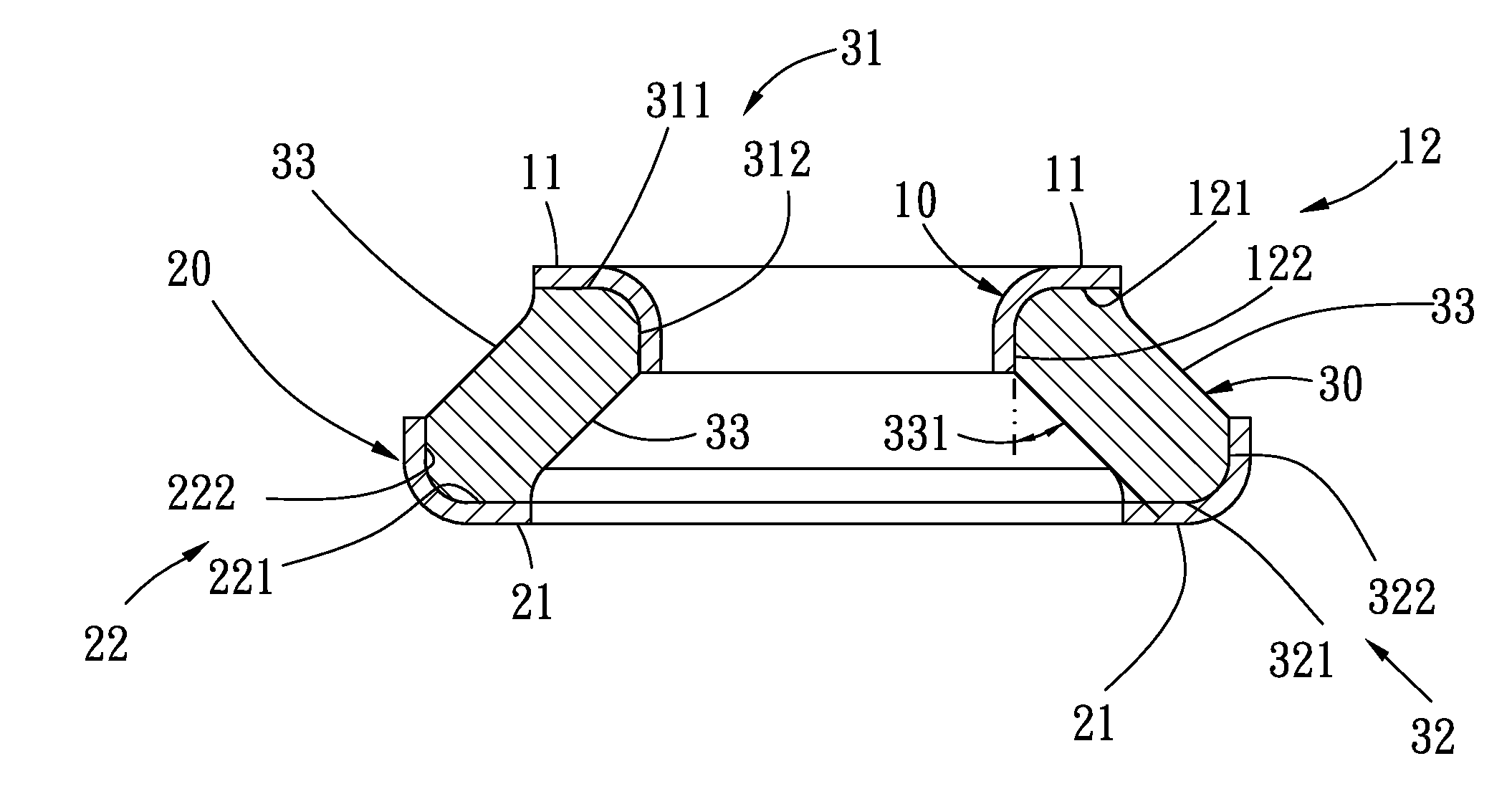
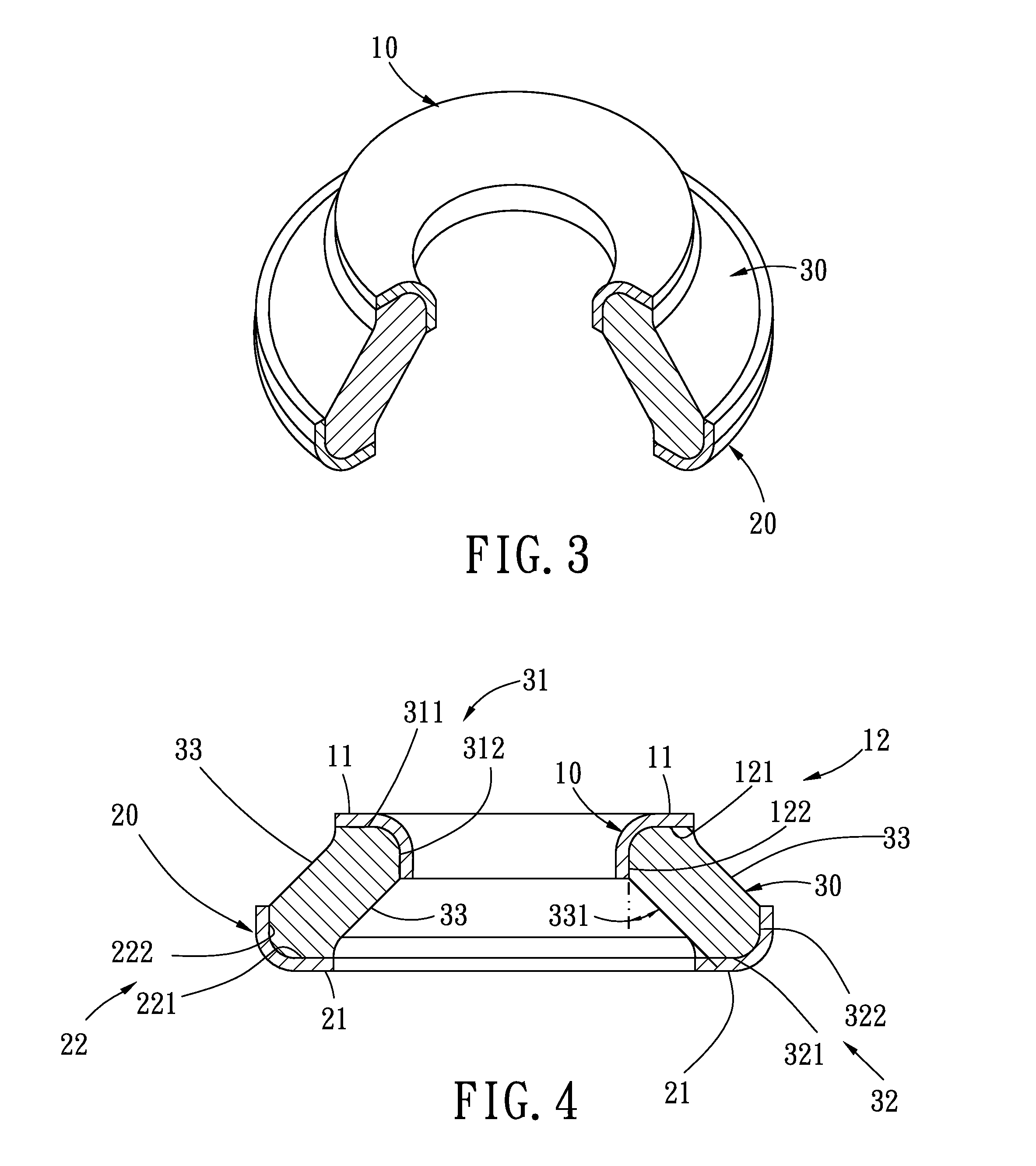
[0043]Referring to FIGS. 3-4, a resilient unit in accordance with the present invention comprises an inner blocking unit 10, an outer blocking unit 20, and an elastomer unit 30. The inner blocking unit 10 is made from hard material. A pressured section 11 is disposed on an outer surface of the inner blocking unit 10 for bearing operating pressure. A securing portion 12 is disposed on an inner surface of the pressured section 11. The securing portion 12 includes a first securing portion 121 and a second securing portion 122.

[0044]The outer blocking unit 20 is made from hard material. Another pressured section 21 is disposed on an outer surface of the outer blocking unit 20 for bearing operating pressure. Another securing portion 22 is disposed on an inner surface of the pressured section 11. The other securing portion 22 includes a third securing portion 221 and a fourth securing portion 222.

[0045]The elastomer unit 30 is made from elastic plastic material or elastic rubber-type mate...


PUM

PropertyMeasurementUnit
Forceaaaaaaaaaa
Pressureaaaaaaaaaa
Resilienceaaaaaaaaaa

Abstract

A resilient structure includes an inner blocking unit, an outer blocking unit, and an elastomer unit. A pressured section is disposed on an outer surface of the inner blocking unit. A securing portion is disposed on an inner surface of the pressured section. Another pressured section is disposed on an outer surface of the outer blocking unit. Another securing portion is disposed on an inner surface of the pressured section. Pressure resisting sections are respectively disposed on an inner and an outer end of the elastomer unit. The pressure resisting sections are respectively confined by the securing portions disposed on the blocking units. A pressure-release portion is formed between the pressure resisting sections of the elastomer unit. The pressure-release portion absorbs pressure and store resilient force for elastic recovery.

Description

BACKGROUND OF THE INVENTION[0001]1. Field of the Invention[0002]The present invention relates to a resilient structure, and more particularly, to a resilient structure comprises an inner blocking unit, an outer blocking unit, and an elastomer unit. By using a securing portion disposed on the inner blocking unit, a pressure-resisting section disposed on an inner end of the elastomer unit is confined; by using a securing portion disposed on the outer blocking unit, a pressure-resisting section disposed on an outer end of the elastomer unit is confined. When the resilient structure is pressured, a pressure-release portion of the elastomer unit absorbs an external pressure and stores a resilient force for elastic recovery.[0003]2. Description of Related Art[0004]Referring to FIGS. 1 and 2, two conventional resilient structures commonly known to the public are: metallic coil spring (as shown in FIG. 1) and rubber resilient unit (as shown in FIG. 2). Both of these resilient structures are...

Claims


Application Information

Patent Timeline
IPC IPC(8): F16F1/36
CPCF16F1/3732F16F3/0876
Inventor HUANG, TAN-CHENG
Owner HUANG TAN CHENG
Why Eureka
Try Eureka