Linear motor

Inactive Publication Date: 2010-07-01
THK CO LTD
View PDF14 Cites 6 Cited by
  • Summary
  • Abstract
  • Description
  • Claims
  • Application Information

AI Technical Summary

Benefits of technology

[0013]The present invention was conceived in consideration of the circumstances encountered in the prior art mentioned above, and an object thereof is to provide a linear motor having a compact and simpl

Problems solved by technology

In an arrangement in which any gap does not exist between the stator and the slider in the linear motor, the stator and the slider are stuck together by the magnetic force generated by supplying the driving current to the armature coil, which may adversely result in impossibility of the relative motion of the slider to the stator, and accordingly, it is necessary to control or manage the gap between the stator and the slider of the linear motor.
However, the structures of the linear motors of the prior art such as mentioned above require guide units or members such as rails extending

Method used


Image

  • Linear motor
  • Linear motor
  • Linear motor

Examples


Example

First Embodiment

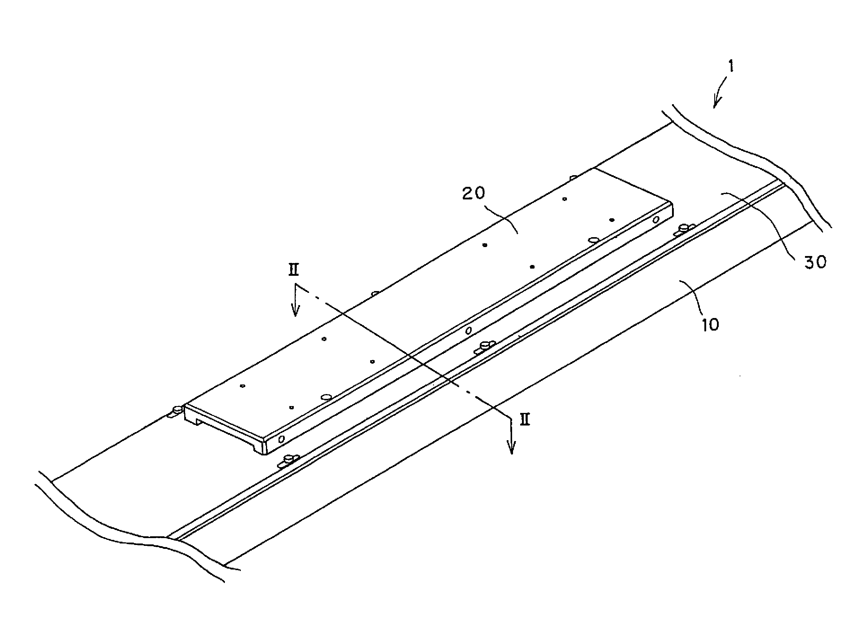
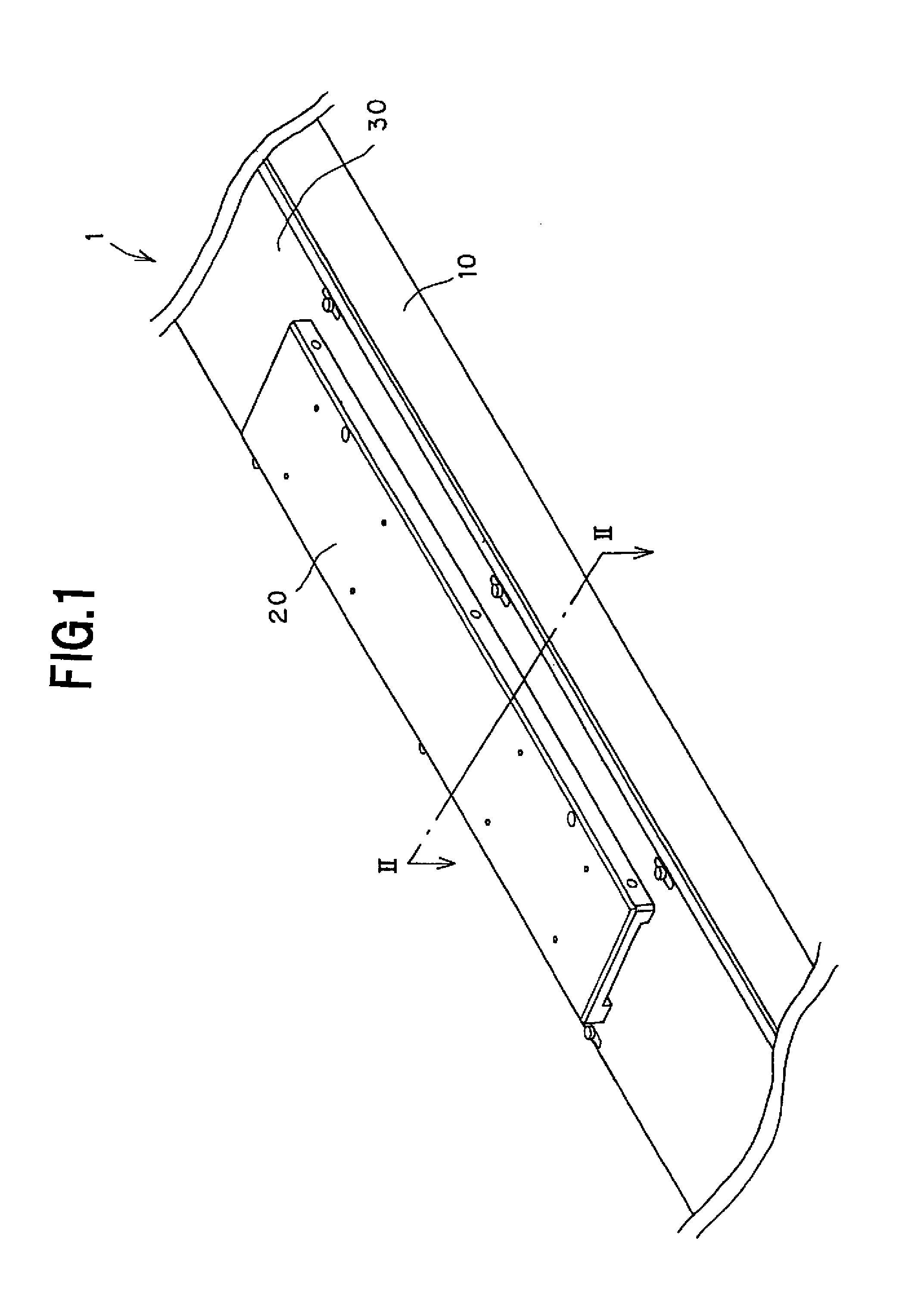
[0039]The first embodiment will be described hereunder with reference to FIGS. 1 to 5.

[0040]As shown in FIG. 1, a linear motor 1 of this first embodiment comprises a stator 10 extending in a longitudinal direction of the linear motor 1, a non-magnetic plate 30 mounted to the stator 10 along its longitudinal direction, and a slider 20 disposed on the non-magnetic plate 30 to be slidably thereon.

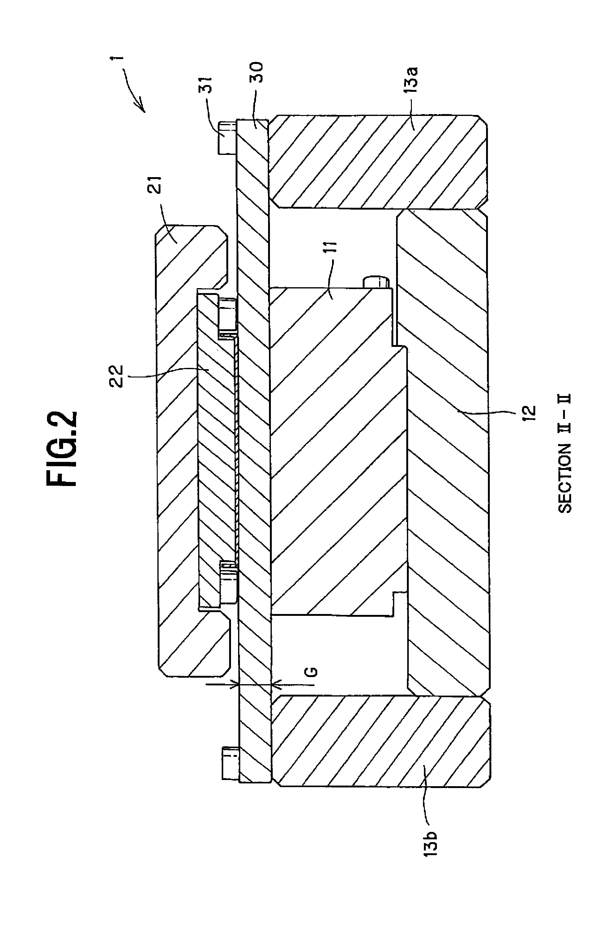
[0041]As shown in FIGS. 1 and 2, the stator 10 is composed of a bottom plate 12 extending along the longitudinal direction thereof, side plates 13a, 13b attached to both end faces of the bottle plate 12 in the width direction thereof so as to stand upward, and armature coil 11 fixed to the upper surface of the bottom plate 12.

[0042]The slider 20 is provided with a movable member 21 to a lower surface of which a magnet 22 is mounted. The non-magnetic plate 30 is attached to the upper surfaces of the side plates 13a, 13b of the stator 10 by means of bolts 31, 31. The slider 20 sl...

Example

Second Embodiment

[0058]As mentioned above, the linear motor 1 in the first embodiment was explained in the case where the magnet 22 is directly slid on the non-magnetic plate 30. In this second embodiment, a motion mode of a slider 20 of a linear motor 2 having different structure from that of the first embodiment will be explained. Further, like reference numerals are added to parts or components corresponding to those of the first embodiment, and duplicated explanation will be omitted herein.

[0059]FIG. 7 is a cross sectional view of the linear motor 2 according to the second embodiment of the present invention, and FIG. 8 is a perspective view of the slider of this linear motor 2.

[0060]As shown in FIG. 7, the linear motor 2 of this second embodiment differs from that of the first embodiment in the structure of the slider 20 (slider 200 in this second embodiment) which is provided with wheels 25.

[0061]As shown in FIG. 8, the slider 200 of the linear motor 2 are provided with the wh...

Example

Third Embodiment

[0065]As mentioned above, the linear motors 1 and 2 in the first and second embodiments were explained in the cases where the slider 20 restrict the motion of the non-magnetic plate(s) 30 in the width direction by the action of the magnetic force generated between the magnet 22 and the armature coil 11.

[0066]A linear motor of the third embodiment performs a guide motion of the slider 20 having a mode different from those in the first and second embodiments. Further, like reference numerals are added to parts or components corresponding to those of the first embodiment, and duplicated explanation will be omitted herein.

[0067]FIG. 9 is a sectional view illustrating structure of the linear motor according to the third embodiment, and as shown in FIG. 9, the linear motor 3 of this third embodiment differs from the second embodiment in that the non-magnetic plate 30 is formed with wheel rolling grooves 32 on which the wheels 25 can roll along the longitudinal direction of...


PUM


Abstract

A linear motor is provided with a stator, a slider disposed to be movable relatively with respect to the stator with a gap, and a non-magnetic plate mounted to either one of the stator and the slider so as to define the gap between the stator and the slider.

Description

BACKGROUND OF THE INVENTION[0001]1. Field of the Invention[0002]The present invention relates to a linear motor provided with a stator and a slider relatively movable with respect to the stator, and more particularly, to a linear motor having a structure capable of easily controlling a gap between the stator and the slider.[0003]2. Related Art[0004]A linear motor has been widely used for a motion guide mechanism or apparatus such as machine tool, industrial robot or the like for moving an object to be moved to a predetermined position with high performance. Such linear motor is generally composed of a stationary member (called hereinlater “stator”) and a movable member (called hereinlater “slider”) in which the slider is supported to the stator to be relatively movable in various arrangement.[0005]A linear motor disclosed in Patent Document 1 (Japanese Patent Application Laid-open Publication No. H09-261943) includes a stator to which a rail is mounted, and a slider is slid along th...

Claims


Application Information

Patent Timeline
IPC IPC(8): H02K41/02
CPCH02K41/03H02K2201/03
Inventor SHODA, KAZUOTOJO, TOSHIRONOMURA, YUKIUNNO, AKIHIRO
Owner THK CO LTD
Why Eureka
Try Eureka