Differential device

A differential device and differential rotation technology, applied in the direction of differential transmission, transmission, power device, etc., can solve the problems of complex device structure, increased device volume, complex structure, etc., and achieve a compact and simple structure. Effect

Pending Publication Date: 2022-03-18
TOYOTA JIDOSHA KK
View PDF1 Cites 0 Cited by
  • Summary
  • Abstract
  • Description
  • Claims
  • Application Information

AI Technical Summary

Problems solved by technology

However, it is not easy to dispose the counter-rotation motor unit between the sun gears while suppressing the enlargement in the radial direction.
For example, the reverse rotation motor unit has a two-shaft structure in which the first output shaft and the second output shaft are arranged parallel to the counter gear shaft, and the structure becomes complicated.
In addition, when a speed reduction mechanism is provided for downsizing the motor or for obtaining a larger torque, the structure of the device becomes further complicated.
In addition, the volume of the device will increase
As a result, it may not be possible to sufficiently improve the mountability on vehicles

Method used


Image

  • Differential device
  • Differential device
  • Differential device

Examples


Embodiment Construction

[0145] Embodiments of the present invention will be described with reference to the drawings. In addition, embodiment shown below is just an example of the case where this invention was actualized, and does not limit this invention.

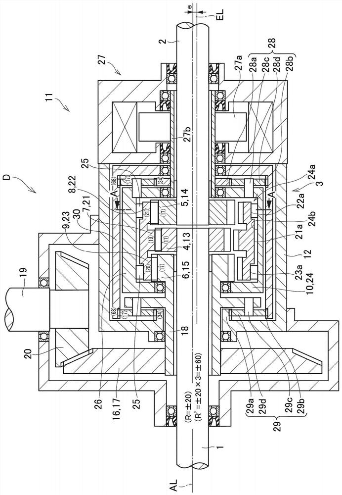
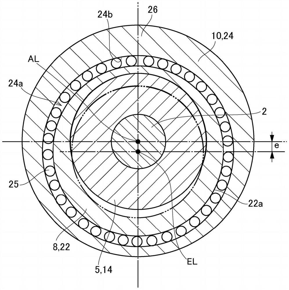
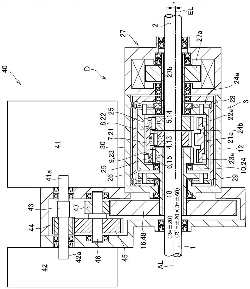
[0146] figure 1 An example of a differential device to which the present invention is applied is shown. The differential device D in the embodiment of the present invention is a transmission device configured to allow two rotating shafts arranged on the same axis to reverse each other and perform differential rotation. The first rotating shaft 1 and the second rotating shaft 2 These two main rotation shafts and the differential rotation mechanism 3 constitute. The differential rotation mechanism 3 includes a first gear 4 , a second gear 5 , a third gear 6 , a first eccentric gear 7 , a second eccentric gear 8 , a third eccentric gear 9 , and an eccentric member 10 as main components. In particular, assuming that it is mounted on a vehicle, the...


PUM


Abstract

The invention provides a differential device which is compact and simple and can be mounted on a vehicle excellently. The first gear, the second gear and the third gear can relatively rotate on the rotation axis; the first eccentric gear is meshed with the first gear; the second eccentric gear is meshed with the second gear; the third eccentric gear is meshed with the third gear; and an eccentric member that integrally supports each eccentric gear so as to be capable of rotating around an eccentric axis line eccentric from the rotation axis line and capable of revolving around the rotation axis line, in the differential device, either one of each gear and each eccentric gear is an internally toothed gear, and the other is an externally toothed gear. The gear ratio between the first gear and the first eccentric gear, the gear ratio between the second gear and the second eccentric gear, and the gear ratio between the third gear and the third eccentric gear are different, and both the rotational speed of the first gear and the rotational speed of the second gear are reduced with respect to the rotational speed of the eccentric member.

Description

technical field [0001] The present invention relates to a differential device capable of differentially rotating two rotating shafts arranged coaxially (for example, left and right drive shafts of a vehicle or a propeller shaft of a four-wheel drive vehicle) in reverse directions relative to each other. Background technique [0002] Patent Document 1 describes an example of a drive gear unit configured using a planetary gear mechanism. The driving gear unit described in this Patent Document 1 is a differential device having a function of so-called torque vectoring, and includes a differential mechanism that distributes and transmits output torque from a driving force source to left and right driving wheels. And a control actuator (motor for control or motor for differential) that controls the torque transmitted from the differential mechanism to the left and right drive wheels. The differential mechanism consists of two sets of single-pinion type planetary gear mechanisms. ...

Claims


Application Information

Patent Timeline
Patent Type & Authority Applications(China)
IPC IPC(8): F16H48/10F16H48/36F16H48/38
CPCF16H48/10F16H48/36F16H48/38F16H57/0006F16H2048/364B60K17/08B60K17/16B60K2001/001B60L50/16B60L2240/48B60L7/10Y02T10/7072B62D11/14B60K17/35
Inventor 矶野宏
Owner TOYOTA JIDOSHA KK
Why Eureka
Try Eureka