Axial flux electrical machine

Active Publication Date: 2010-07-01
REGAL BELOIT AUSTRALIA PTY LTD
View PDF19 Cites 26 Cited by
  • Summary
  • Abstract
  • Description
  • Claims
  • Application Information

AI Technical Summary

Benefits of technology

[0014]In one embodiment, the housing includes an end shield and the secondary bearing is fixed to the shaft at a location outside of the end shield. The wave washer is then positioned between an outward facing surface of the end shield and the secondary bearing. In this way, the wave washer serves to push the secondary bearing, and the shaft to which it is connected, away from the main bearing.
[0015]The secondary bearing may be fixed to the sha

Problems solved by technology

Axial flux motors do not ideally suit this kind of bearing because a large amount of axial (or thrust) load is present on one bearing within an axial flux motor due to the large amount of attractive force between the rotor and stator.
The high thrust load

Method used


Image

  • Axial flux electrical machine
  • Axial flux electrical machine
  • Axial flux electrical machine

Examples


Embodiment Construction

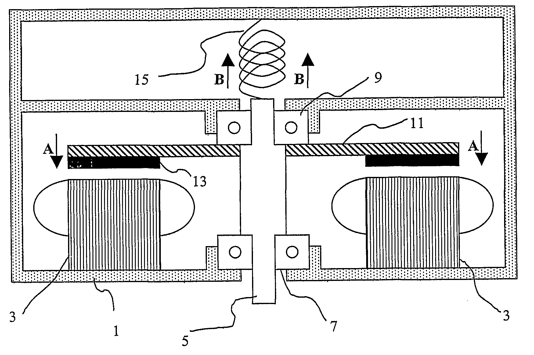
[0025]Referring initially to FIG. 1 of the drawings, there is shown a schematic representation of an axial flux direct current (DC) motor. The motor includes a housing 1, a stator 3 located within the housing 1, a rotatable shaft 5 carried by the housing 1 by means of a main bearing 7 and a secondary bearing 9. The motor also includes a rotor 11 fixed to the shaft 5 and has permanent magnets 13 attached to the rotor. Magnetic attractive forces between the magnets 13 on the rotor 11 and the stator 3 produce an axial thrust in the direction “A” on the main bearing 7. The motor further includes a biasing means, represented as a spring 15, which is arranged to urge the shaft 5 in the direction “B” so as to reduce the net load on the main bearing 7.

[0026]It will be appreciated from the somewhat idealised representation in FIG. 1 that the invention is based on the principle of applying a force to the shaft 5 in a direction which is opposite to the direction of the magnetic force. This may...


PUM


Abstract

An axial flux electrical machine including a housing, a stator located within the housing, a rotatable shaft carried by the housing by means of at least a main bearing, and a rotor fixed to the shaft within the housing. Magnetic attractive forces between the rotor and the stator produce an axial thrust on the main bearing and a biasing means (preferably in the form of a spring) is arranged to urge the shaft in a direction opposite to the axial thrust so as to reduce the net load on the main bearing. This reduction in net load on the main bearing increases bearing life and improves motor efficiency.

Description

FIELD OF THE INVENTION[0001]The present invention relates generally to electrical machines and, in particular, to axial flux electrical machines. The invention is especially suited for use in axial flux electric motors and it will therefore be convenient to describe the invention with relation to that example application. It should be understood however that the invention is equally as applicable to axial flux generators.BACKGROUND OF THE INVENTION[0002]Electric motors generally require two bearings. Ideally, the bearings used are as low cost as possible. Of the rolling bearing family, deep-groove ball bearings are generally the lowest cost. Axial flux motors do not ideally suit this kind of bearing because a large amount of axial (or thrust) load is present on one bearing within an axial flux motor due to the large amount of attractive force between the rotor and stator. The more common radial flux motor structure does not have this issue, the force being reasonably balanced within...

Claims


Application Information

Patent Timeline
IPC IPC(8): H02K7/08H02K5/16
CPCH02K7/083H02K21/24F16C39/02F16C2380/26F16C19/54
Inventor LANGFORD, CHARLES RICHARDCAMILLERI, STEVEN PETER
Owner REGAL BELOIT AUSTRALIA PTY LTD
Why Eureka
Try Eureka