
Transforming apparatus for automatically adjusting three-phase power supply voltage

a technology of power supply voltage and transformer, which is applied in the direction of electric variable regulation, ac network circuit arrangement, instruments, etc., can solve the problems of unstable power supply voltage at the receiving point of power consumers, large electric power consumption, and equipment, so as to ensure the stability and reliability of switching operation timings.

Inactive Publication Date: 2010-07-01
POWERPERFECTOR
View PDF2 Cites 3 Cited by
  • Summary
  • Abstract
  • Description
  • Claims
  • Application Information

AI Technical Summary

Benefits of technology

Problems to be Solved by the Invention
[0007]An object of the present invention is to provide a transforming apparatus with a Y-connection three-phase transformer as its basic configuration which automatically adjusts the voltage of three-phase power supply to within a target voltage range lower than the rated voltage and supplies to load equipment.
Means for Solving the Problems

Problems solved by technology

In, for example, hotels, supermarkets, factories, etc., lighting equipment, air conditioning equipment, power equipment, or the like consumes a large amount of electric power.
In areas which are inferior in the stability of power generating facilities and power distribution facilities, power supply voltage at receiving points of power consumers is not stable and often fluctuates over a voltage range slightly higher than the rated voltage.

Method used


Image

  • Transforming apparatus for automatically adjusting three-phase power supply voltage
  • Transforming apparatus for automatically adjusting three-phase power supply voltage
  • Transforming apparatus for automatically adjusting three-phase power supply voltage

Examples


Embodiment Construction

[0073]===Outline of the Transforming Apparatus===

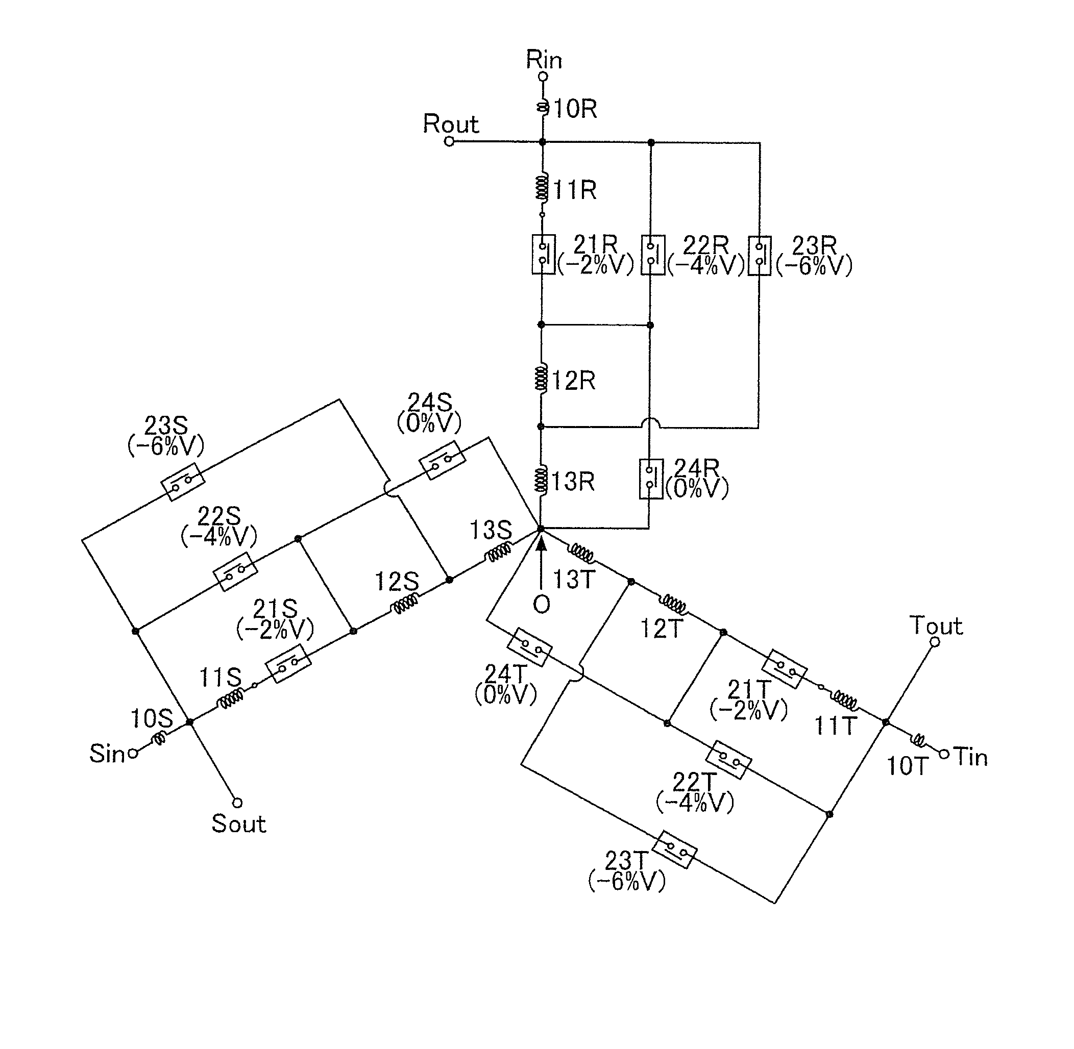
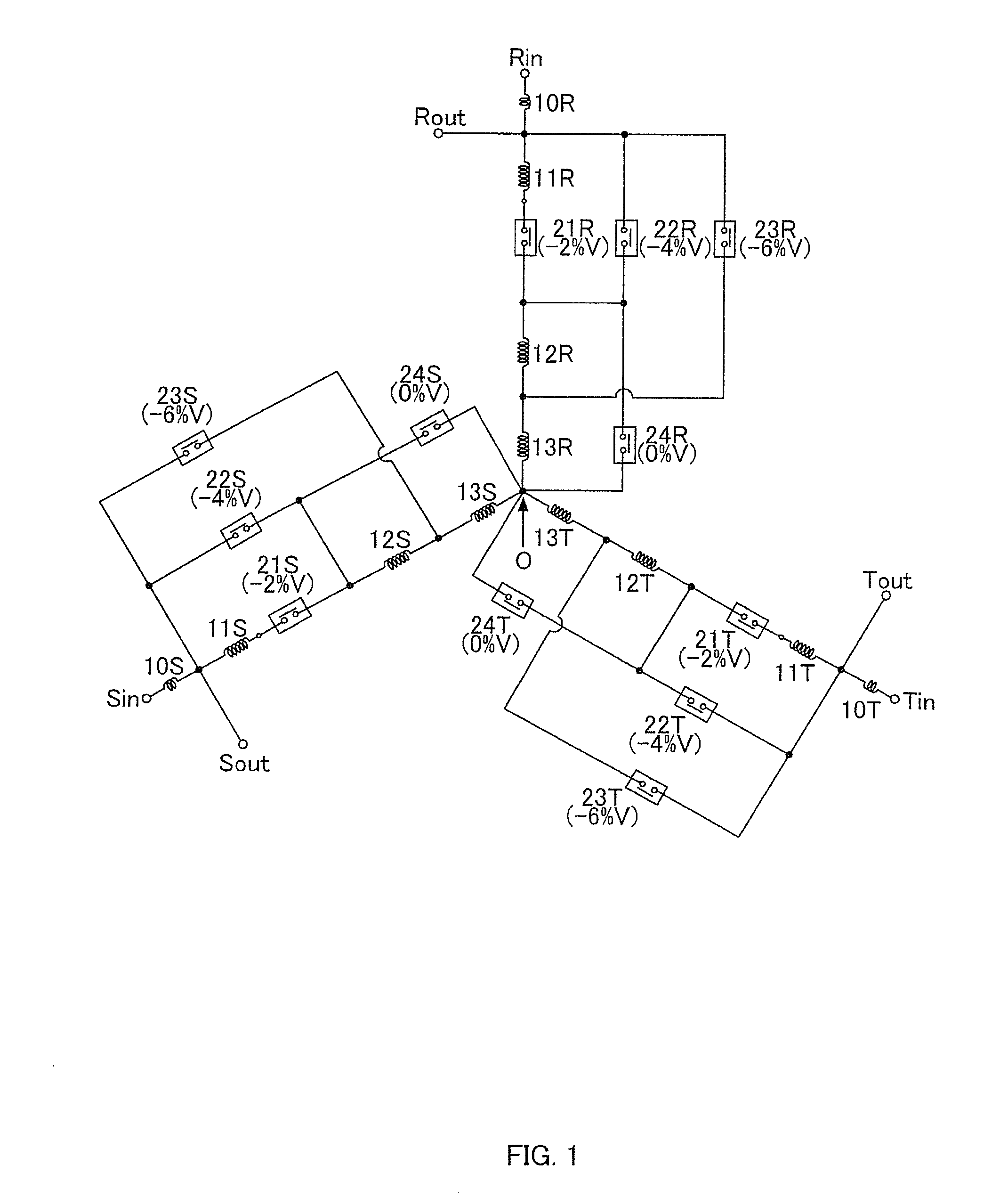
[0074]FIG. 1 shows the winding configuration of a transforming apparatus according to the present invention, and FIG. 3 shows the configuration of a switch switching circuit 8. First, the overall outline of this transforming apparatus will be described.

[0075]This transforming apparatus comprises three input terminals Rin, Sin, Tin connected respectively to the three main lines of three-phase power supply and three output terminals Rout, Sout, Tout connected to a load installation. The transforming apparatus switches between a first mode where the output voltage is made about 2% lower than the input voltage, a second mode where the output voltage is made about 4% lower than the input voltage, a third mode where the output voltage is made about 6% lower than the input voltage, and a fourth mode where the output voltage is substantially equal to the input voltage in an alternative manner.

[0076]The transforming apparatus comprises, as its...


PUM


Abstract

A transforming apparatus automatically adjusting the voltage of three-phase power supply comprising three input terminals, three output terminals, a Y-connection three-phase transformer, a switch group, and a switch switching circuit. The three input terminals are respectively connected to three main lines of the three-phase power supply, and the three output terminals are connected to a load installation. The Y-connection three-phase transformer comprises a core, an R-phase winding circuit, an S-phase winding circuit, and a T-phase winding circuit. In the R-phase winding circuit, an R-phase main winding, an R-phase first auxiliary winding, an R-phase first switch, an R-phase second auxiliary winding, and an R-phase third auxiliary winding are serially connected in that order between the input terminal Rin and a neutral point O, the output terminal Rout being connected to the other end of the R-phase main winding. An R-phase second switch is connected in parallel with a series circuit of the R-phase first auxiliary winding and the R-phase first switch. An R-phase third switch is connected in parallel with a series circuit of the R-phase first auxiliary winding, the R-phase first switch, and the R-phase second auxiliary winding. An R-phase fourth switch is connected in parallel with a series circuit of the R-phase second auxiliary winding and the R-phase third auxiliary winding. The switch switching circuit controls the switches based on the voltage levels of the output terminals to switch between first to fourth modes in an alternative manner.

Description

TECHNICAL FIELD[0001]The present invention relates to a transforming apparatus which automatically adjusts the voltage of three-phase power supply led into a power consumer site to within a target voltage range lower than its rated voltage and supplies to load equipment, and particularly to such a transforming apparatus which has a Y-connect ion three-phase transformer as its basic configuration.BACKGROUND ART[0002]In, for example, hotels, supermarkets, factories, etc., lighting equipment, air conditioning equipment, power equipment, or the like consumes a large amount of electric power. Recently, such general power consumers have strongly recognized the necessity for energy saving measures, and various measures have been come up with and are being carried out.[0003]One of energy saving measures adoptable by general power consumers is a known scheme where the electricity receiving system leading commercial power supply into indoor equipment is provided with the transforming apparatu...

Claims


Application Information

Patent Timeline
IPC IPC(8): G05F1/20
CPCH01F29/02H01F30/12H02J3/1878H02P13/06Y02E40/30
Inventor SHIMAZU, CHIYUKITSUNEMI, SEIJI
Owner POWERPERFECTOR
Learn More