Electromagnetic piezoelectric acoustic sensor

a piezoelectric acoustic sensor and electromagnet technology, applied in the direction of magnetic property measurement, instruments, material magnetic variables, etc., can solve the problems of achieve the goal of ensuring the sensitivity of the device, ensuring the robustness, and restricting any sensitivity improvement

Inactive Publication Date: 2010-07-01
CAMBRIDGE ENTERPRISE LTD
View PDF8 Cites 11 Cited by
  • Summary
  • Abstract
  • Description
  • Claims
  • Application Information

AI Technical Summary

Benefits of technology

[0017]An important advantage of the present invention is that the inventors have found a solution to the sensitivity limitation of conventional acoustic resonator sensors. The sensitivity of these devices could theoretically be improved, but this would have demanded acoustic sensors thinner than 200 μm. This limitation formerly restricted any sensitivity improvement, because the devices became too fragile. However the present invention has no such limitation as it allows sensing devices to shrink laterally as well as in the thickness direction, by using fragments or particles, so robustness is maintained. For example a 1 μm thick device will have 200 times the mass sensitivity of a 200 μm thick device.
[0018]The sensing apparatus of the invention can be used in arrays, microfluidic systems, tubes, reaction vessels and as RFID smart tags avoiding transport of the sample to the measurement instrument for analysis. Complicating wires or connections are avoided benefiting measurement applications in small reaction chambers, microfluidic chamber or subcutaneously. The invention uses a radio link to wireless acoustic sensors that are supremely simple. They provide the user with a freedom similar to mobile phones. Here an electrically active material alone, with no support of any kind, can behave as a receiver, acoustic sensor, transmitter and antenna. The sensing elements cannot run out of power or fail as the intrinsic property of the material does not disappear. The improved and sharper resonances of the smaller sensor fragments are illustrated in the examples herein, whilst it is demonstrated that quartz fragments can be placed in a fluid filled beaker that is linked by radio to a toroidal antenna. This demonstrates that the sensing element can be made smaller, boosting sensitivity inversely to its thickness. Thus gains in sensitivity of 100 fold or more can be achieved while reducing any strain on the environment it is located in. Non-biological applications involving smart tags, temperature sensitivity, viscosity sensitivity, humidity, spoilage, cars, engines, aeronautics and space are also envisaged.
[0019]The invention will now be described in more detail, by way of example only, with reference to the following figures, in which
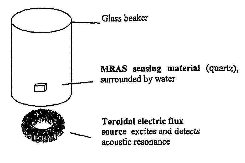
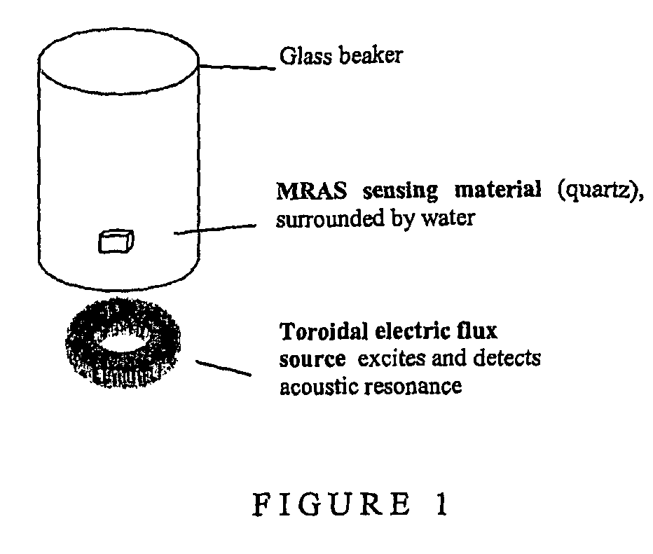
[0020]FIG. 1 shows a test format used to excite piezoelectric disc and fragments inside a glass beaker; the source is a toroidal transformer, which generates electric flux to both excite vibration in the disc, and to detect this vibration;
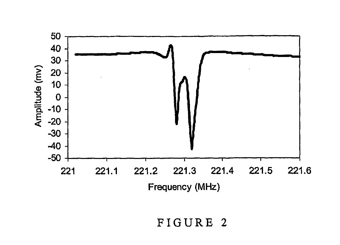
[0021]FIG. 2 shows a harmonic acoustic resonance in a 12 mm diameter 0.25 mm thick piezoelectric AT quartz disc (in air); there are two side resonances that correspond to nanometre-sized thickness differences across the disc, created by a typical lapping process;
[0022]FIG. 3 shows the more defined acoustic resonance of a 2×2 mm AT quartz fragment (in air) sourced from the ‘broken’ 12 mm disc of FIG. 2;

Problems solved by technology

This limitation formerly restricted any sensitivity improvement, because the devices became too fragile.

Method used


Image

  • Electromagnetic piezoelectric acoustic sensor
  • Electromagnetic piezoelectric acoustic sensor
  • Electromagnetic piezoelectric acoustic sensor

Examples


examples

[0052]Materials and Methods

[0053]Discs

[0054]Piezoelectric AT crystal blanks 12 mm in diameter and 0.25 mm thick were prepared to a fine optical polish. Devices were cleaned in chloroform, then acetone and finally isopropanol.

[0055]Fragments

[0056]The same piezoelectric crystal was also broken into approximately 40 to 50 pieces for testing. All fragments had resonance frequencies and amplitudes that would different from each other.

[0057]Beads

[0058]Beads or fragments with chemical coatings provide an ideal opportunity for accessing wirelessly chemical environments in tubes, chambers, microfluidics and arrays used in biotechnology. They can be frequency ‘tagged’ so that a large number of sensors can be scanned with a single coil.

[0059]Measurement Equipment

[0060]Toroid Z Measurements

[0061]The equipment selected for the measurement was the Hewlett Packard impedance analyser which operates at up to 1.8 GHz. It allows sample positioning at the measurement head so cable contributions to the ...


PUM

PropertyMeasurementUnit
diameteraaaaaaaaaa
thicknessesaaaaaaaaaa
diameteraaaaaaaaaa

Abstract

Provided is a remote sensing apparatus comprising: (a) an electromagnetic field detector and (b) an acoustic resonator comprising an electromagnetic field generator and a sensing material in wireless communication with the generator; wherein the sensing material is in wireless communication with the detector, and an acoustic property of the sensing material is responsive to a change in state of an environment to which the sensing material is exposed, and wherein the sensing material is in the form of one or more particles and/or fragments.

Description

FIELD OF INVENTION[0001]The present invention concerns a remote sensing apparatus, in particular a remote sensor employing an acoustic resonator wirelessly coupled to a detector. The invention also relates to methods and devices employing the sensors. An advantage of the apparatus of the present invention is that the sensing element which is situated remotely in an environment to be investigated cannot run out of power or fail, since the intrinsic property of the material does not disappear. Accordingly, the sensor may be implanted in a remote environment without the need for subsequent explantation for maintenance. The sensing apparatus also exhibits improved and sharper resonances by employing smaller sensor fragments, with sensitivity enhanced 100 fold or more.[0002]BACKGROUND TO THE INVENTION[0003]Acoustic sensors that employ resonators have been used as detection devices for the past several decades, exhibiting sensitivity in the ng / ml range. They share with optical devices an ...

Claims


Application Information

Patent Timeline
Patent Type & Authority Applications(United States)
IPC IPC(8): G01N27/72G01N27/00G01N29/12
CPCG01N29/12G01N2291/014G01N2291/02416G01N2291/0421G01N2291/0422G01N2291/101
Inventor LOWE, CHRISTOPHER ROBINSTEVENSON, ADRIAN CARLARAYA-KLEINSTEUBER, BERNARDITA
Owner CAMBRIDGE ENTERPRISE LTD
Why Eureka
Try Eureka