
Remote phosphor LED illumination system

Inactive Publication Date: 2010-07-01
OSRAM SYLVANIA INC
View PDF12 Cites 68 Cited by
  • Summary
  • Abstract
  • Description
  • Claims
  • Application Information

AI Technical Summary

Benefits of technology

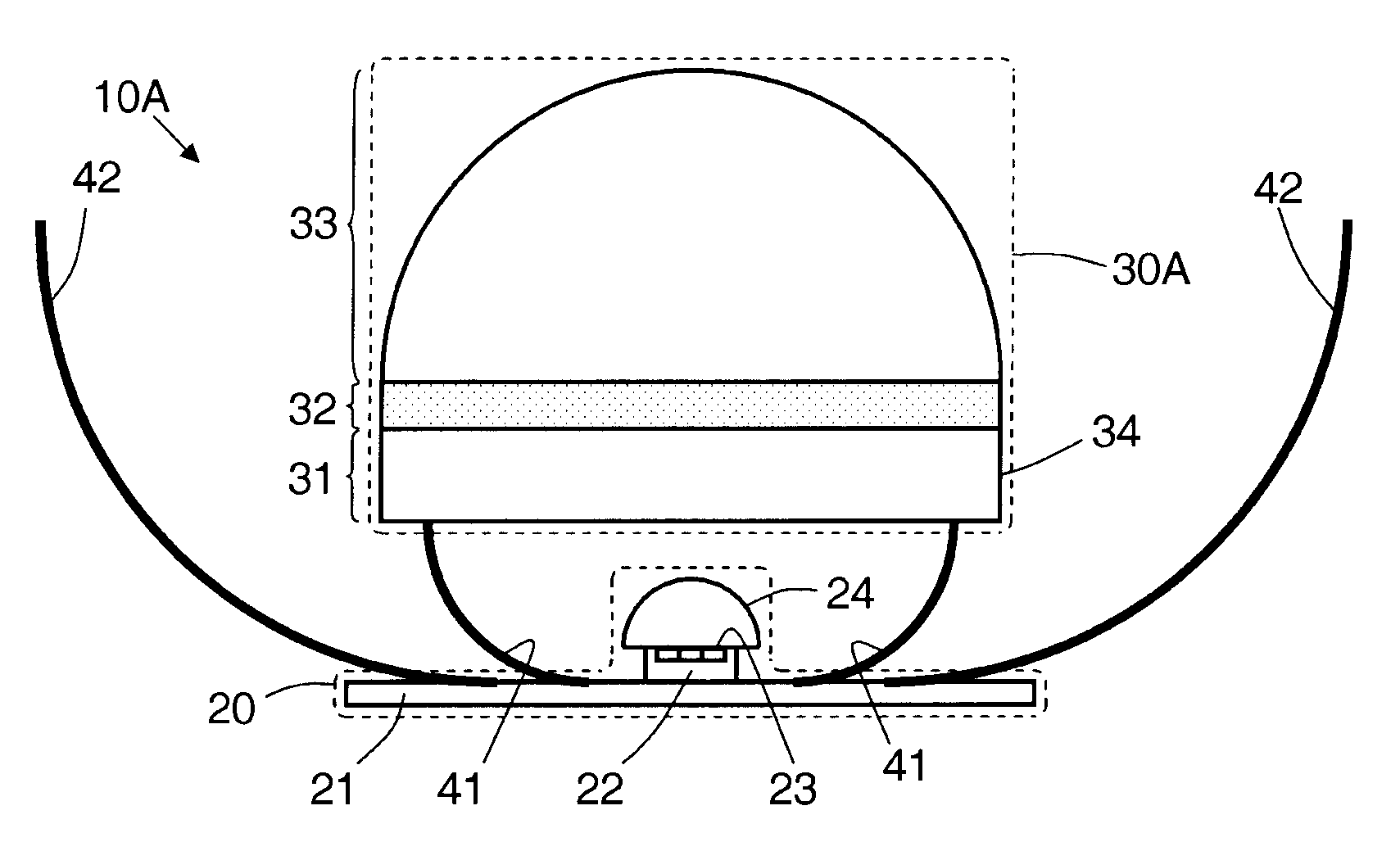
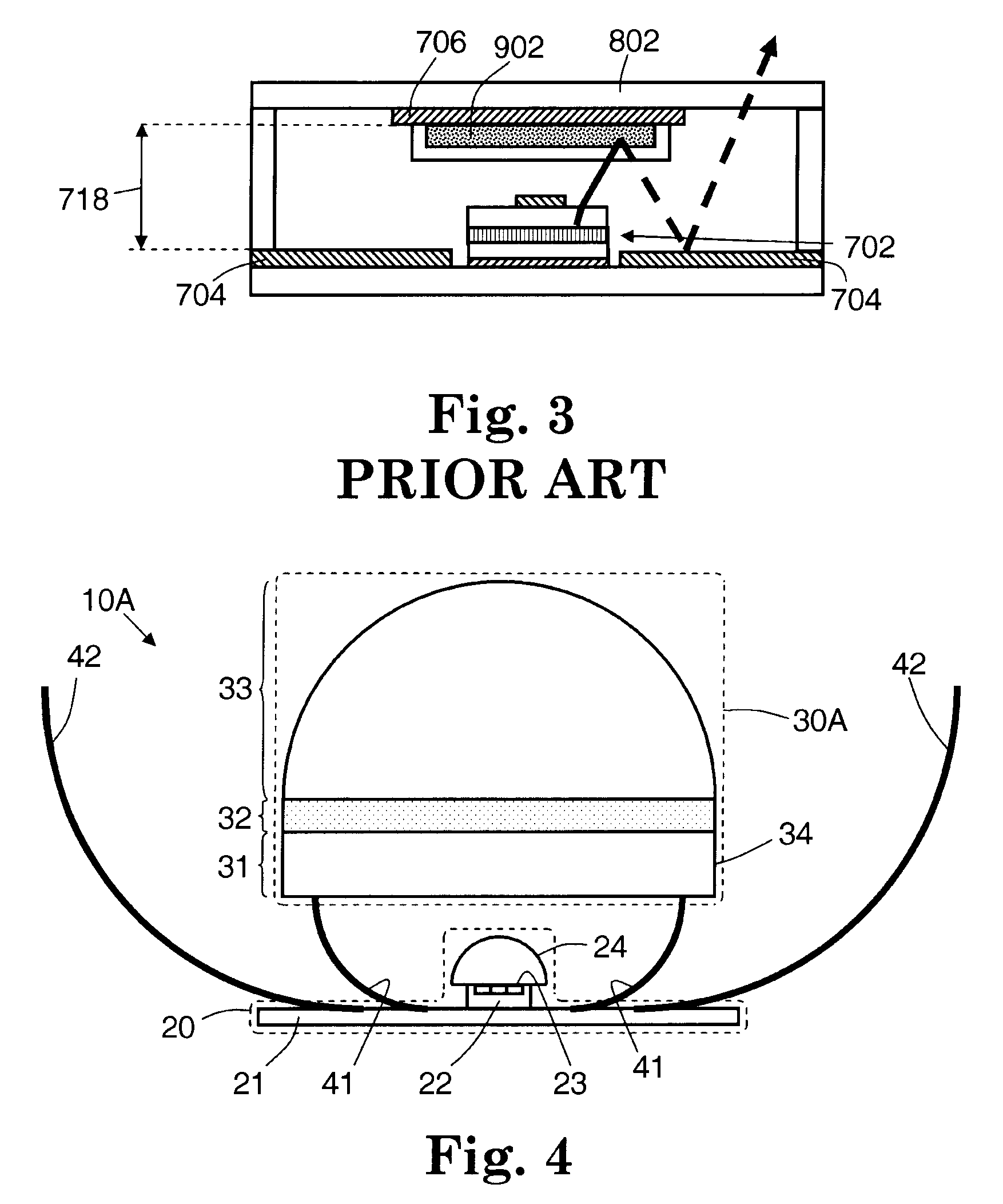
[0027]An embodiment is an illuminator, comprising: a light-emitting diode module having an LED emission plane for emitting short-wavelength light; a phosphor module longitudinally spaced apart from the light-emitting diode module and including a phosphor layer for absorbing short-wavelength light and emitting wavelength-converted light; an inner reflector circumferentially surrounding the LED emission plane and extending from the LED emission plane to the phosph

Problems solved by technology

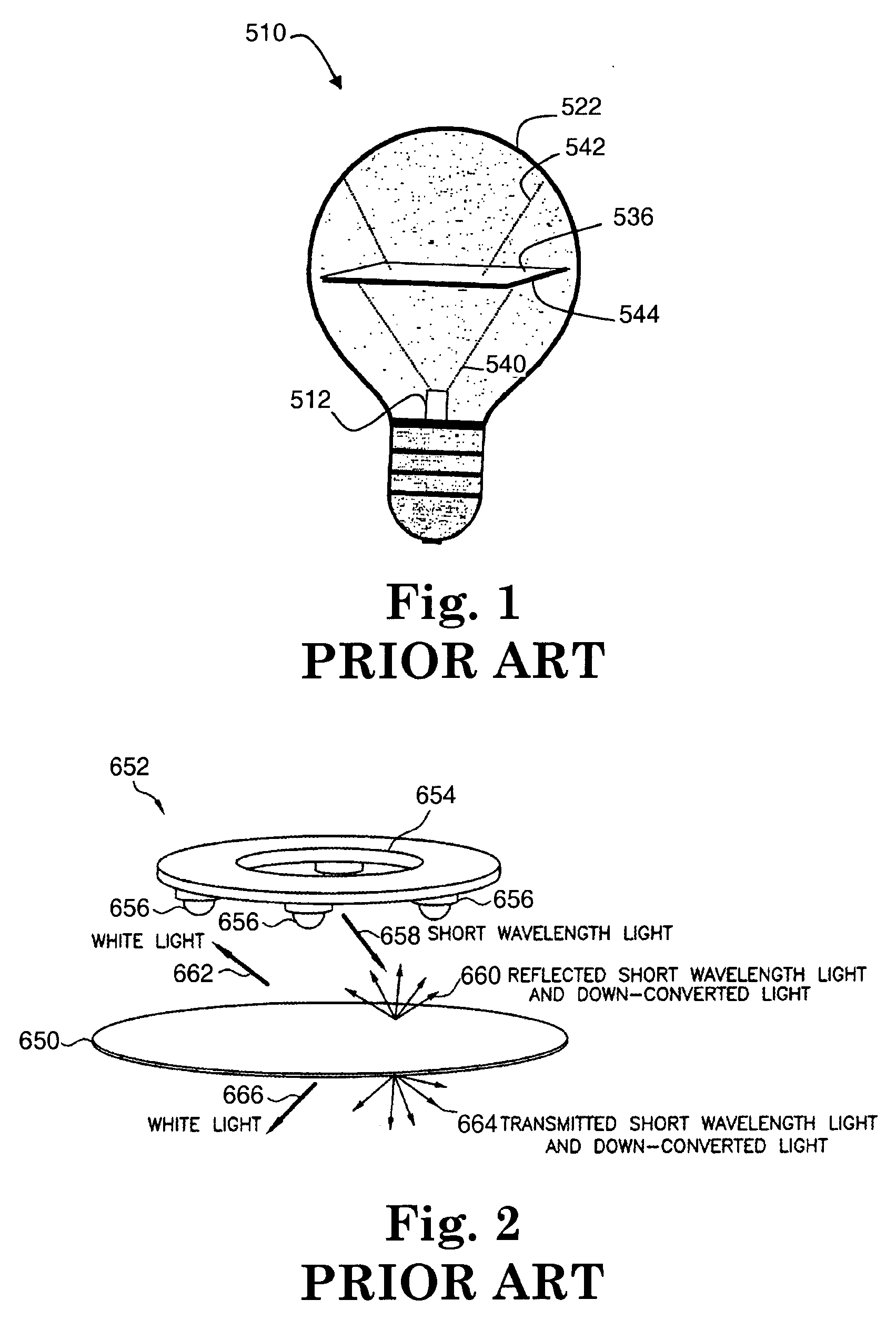
In general, the known optical systems fail to provide an LED-based illuminator that has both a high fixture efficiency (i.e., a high percentage of light leaving the blue LED that strikes the phosphor) and a relatively narrow beam angle (i.e., a relatively small angular distribution of exiting light, compared to a Lambertian distribution).
This results in a reduced efficiency in the fraction of LED emission that is delivered to the phosphor, which may be significantly less than 100%.
In general, light emitted from a planar phosphor has a relatively wide angular distribution, which may be considered too wide for some applications.
Second, the angular distribution of the white light may be especially wide, and even moreso compared with the device of Bohler since there is both transmitted and reflected light propagating away from the phosphor toward the viewer.
This angular distribution may be too wide for some applications.

Method used


Image

  • Remote phosphor LED illumination system
  • Remote phosphor LED illumination system
  • Remote phosphor LED illumination system

Examples


Embodiment Construction

[0043]In many illuminators, light from a short-wavelength light-emitting diode (LED) is transmitted to a phosphor. The phosphor absorbs the short-wavelength light and emits wavelength-converted light, which may have a desired wavelength spectrum that largely depends on the chemistry of the phosphor. For some applications, it may be desirable to increase the efficiency between the LED and the phosphor, so that as much LED light as possible is absorbed by the phosphor. It may also be desirable to narrow the angular distribution of the light emitted by the phosphor, so that the light is narrower than the typical Lambertian distribution, which has a full-width-at-half-maximum (FWHM) of 120 degrees. Note that in some applications, some of the illuminating short-wavelength light may exit the device along with the phosphor-emitted light; in these cases, the total emission spectrum of the device may include a blue contribution from the illuminating LED and a yellow / red contribution from the...


PUM


Abstract

An illuminator is disclosed, in which an LED module emits short-wavelength light toward a phosphor module, which absorbs it and emits wavelength-conditioned light. The emission is generally longitudinal, with a generally Lambertian distribution about the longitudinal direction. The phosphor module includes a transparent layer, closest to the LED module, and a phosphor layer directly adjacent to the transparent layer. Both layers are oriented generally perpendicular to the longitudinal direction. The illuminator includes a reflector, circumferentially surrounding the emission plane in the LED module and extending longitudinally between the emission plane and the transparent layer. Virtually all the light emitted from the LED module either enters the phosphor module directly, or enters after a reflection off the reflector. The transverse side or sides of the transparent layer support total internal reflection, so that virtually all the light that enters the transparent layer, from the LED module, is transmitted to the phosphor layer. In some applications, the phosphor layer is located at the focus of a concave mirror, which can narrow and / or collimate the light emitted by the phosphor. Adjacent to the phosphor layer and opposite the transparent layer, the phosphor module can include a transparent dome, a heat sink, or nothing.

Description

CROSS-REFERENCE TO RELATED APPLICATIONS[0001]Not ApplicableSTATEMENT REGARDING FEDERALLY SPONSORED RESEARCH OR DEVELOPMENT[0002]Not ApplicableBACKGROUND OF THE INVENTION[0003]1. Field of the Invention[0004]The present invention is directed to an LED-based phosphor illuminator.[0005]2. Description of the Related Art[0006]Light emitting diodes (LEDs) are rapidly finding acceptance in many lighting applications. Compared with incandescent light bulbs, LEDs are more efficient, have longer lifetimes, and may be packaged in a wide variety of suitably shaped and sized packages.[0007]In particular, so-called white-light LEDs are become more popular for illumination applications. In these white-light LEDs, the light-producing element is typically an LED that emits light at a relatively short wavelength, such as blue, violet, or UV. The light emitted from the so-called blue LED strikes a phosphor. The phosphor absorbs the blue light and emits light at one or more longer wavelengths, which may...

Claims


Application Information

Patent Timeline
IPC IPC(8): F21V9/16F21V9/40
CPCF21V7/0025F21V29/74F21Y2115/10F21K9/64F21K9/68F21V9/30
Inventor ALLEN, STEVEN C.
Owner OSRAM SYLVANIA INC
Learn More