Method, device, and system for polarization division multiplexing and demultiplexing

a technology of polarization division and multiplexing, applied in the field of communication, can solve the problems of random rotation and differential group delay (dgd) to the polarization state, no measure for avoiding, and incorrect demultiplexing

Inactive Publication Date: 2010-07-01
HUAWEI TECH CO LTD
View PDF5 Cites 25 Cited by
  • Summary
  • Abstract
  • Description
  • Claims
  • Application Information

AI Technical Summary

Benefits of technology

[0033]Therefore, in the embodiments of the present invention, an identification signal is loaded at a PDM end, an identification signal carried on a corresponding polarization branch is detected at a polarization division demultiplexing end, and polarization control is performed on a PDM signal according to the detected identification signal, so as to avoid reversal reception of two polarization branches during polarization division demultiplexing, thereby ensuring correct polarization division demultiplexing during reception.

Problems solved by technology

However, due to the polarization effect in an optical-fiber link, when an optical signal is transmitted in the optical fiber, random rotation and differential group delay (DGD) may occur to the polarization state.
Moreover, in the case of a combination of various effects such as non-linearity and dispersion, mutual interferences and aliasing may also occur between two PDM branches, causing incorrect demultiplexing.
That is to say, no measure for avoiding reverse reception of two polarization branches is provided, and this solution is also unable to control such continuous reversal of polarization branches that randomly occurs.

Method used


Image

  • Method, device, and system for polarization division multiplexing and demultiplexing
  • Method, device, and system for polarization division multiplexing and demultiplexing
  • Method, device, and system for polarization division multiplexing and demultiplexing

Examples


Embodiment Construction

[0043]In order to make it easier for persons of ordinary skill in the art to understand and implement the present invention, embodiments of the present invention are described below with reference to the accompanying drawings. Here, the exemplary embodiments of the present invention and descriptions thereof are intended to illustrate the present invention, instead of limiting the present invention.

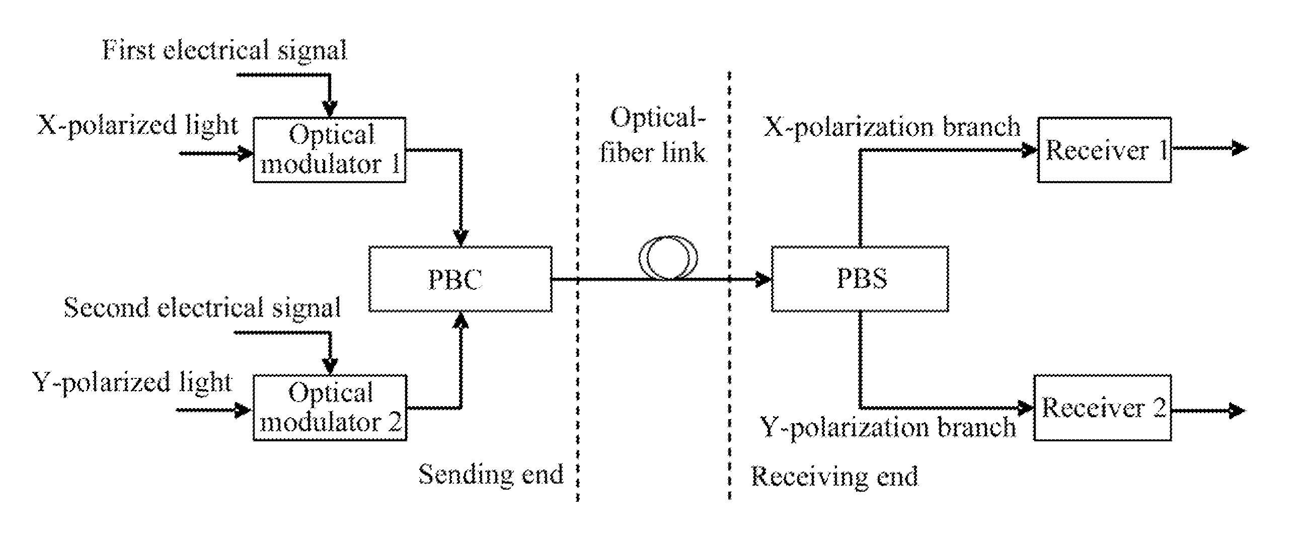
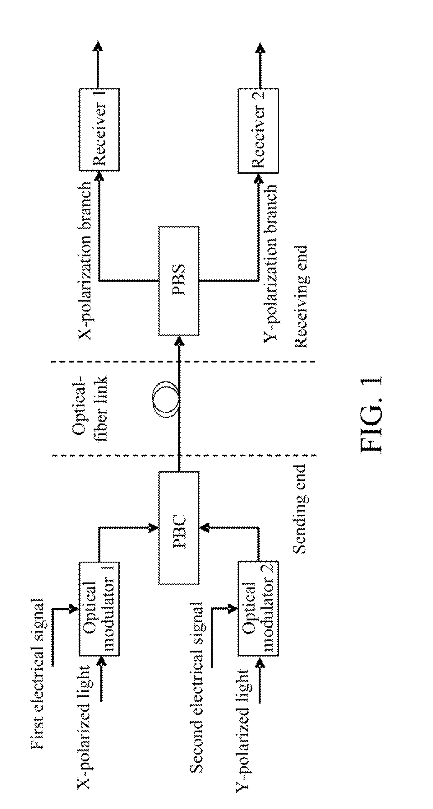
[0044]In an embodiment, the present invention provides a method for PDM, which includes the following steps.

[0045]Polarization division is performed on an optical carrier to obtain an X-polarized light and a Y-polarized light having polarization states orthogonal to each other.

[0046]The X-polarized light is modulated and loaded with a first identification signal to obtain a first optical signal.

[0047]The Y-polarized light is modulated with a second electrical signal to obtain a second optical signal.

[0048]Polarization combination is performed on the first optical signal and the second opti...


PUM


Abstract

A method, device, and system for polarization division multiplexing (PDM) and polarization division demultiplexing are provided in the field of communication and transmission. The device for polarization division demultiplexing includes a polarization controller (PC), a polarization beam splitter (PBS), a detection control module, an optoelectronic receiver 1, and an optoelectronic receiver 2. The PC is adapted to receive a PDM optical signal carrying an identification signal and perform polarization control on the PDM optical signal. The PBS is adapted to perform polarization division on the PDM optical signal carrying the identification signal after the polarization control. The detection control module is adapted to perform identification signal detection on the optical signal after the polarization division to obtain a power of the identification signal, and output a polarization control signal to control the PC according to a power change of the identification signal. The optoelectronic receiver 1 and the optoelectronic receiver 2 are adapted to perform demodulation reception on an X-polarization branch optical signal and a Y-polarization branch optical signal respectively to obtain a first original signal and a second original signal. Thereby, during polarization division demultiplexing, reversal of two demultiplexed polarization branches is effectively avoided.

Description

CROSS-REFERENCE TO RELATED APPLICATIONS[0001]This application claims priority to Chinese Patent Application No. 200810242164.X, filed on Dec. 30, 2008, which is hereby incorporated by reference in its entirety.FIELD OF THE TECHNOLOGY[0002]The present invention relates to the field of communication, and more particularly to a method, device, and system for polarization division multiplexing (PDM) and polarization division demultiplexing.BACKGROUND OF THE INVENTION[0003]With the development of high-speed optical fiber transmission technology, polarization division multiplexing (PDM) technology is needed to enhance the spectral efficiency. The PDM technology allows different optical signals to be modulated respectively on two orthogonal polarization states at the same wavelength, thus increasing the transmission rate in the case of occupying the same band.[0004]FIG. 1 is a system structure in which the PDM technology is applied. Taking a system with a single-wave bit rate of 40 Gb / s as...

Claims


Application Information

Patent Timeline
Patent Type & Authority Applications(United States)
IPC IPC(8): H04J14/06
CPCH04J14/0279H04J14/06H04J14/0258H04J14/0276
Inventor CHANG, DEYUANFANG, YUANYUANZHAO, CHANXIONG, QIANJIN
Owner HUAWEI TECH CO LTD
Why Eureka
Try Eureka