Fuel cell stack having an integrated end plate assembly

Active Publication Date: 2010-07-01
AUDI AG
View PDF8 Cites 9 Cited by
  • Summary
  • Abstract
  • Description
  • Claims
  • Application Information

AI Technical Summary

Benefits of technology

[0010]The integrated end plate assembly also includes a backbone having a plurality of tie-rod ends defining throughbores configured to receive and secure tie rods adjacent a perimeter of the fuel cell stack. The backbone includes at least one beam that extends between the tie-rod ends. The backbone is secured adjacent the backbone-support plane of the pressure plate, and the beam contacts and extends along the backbone-support plane so that the pressure plate is secured between the backbone and the current collector. The tie-rod ends of the backbone overlie the deflection plane of the pressure plate to thereby define a gap between the tie-rod ends and the deflection plane. The backbone has adequate flexibility to permit expansion of the fuel cell stack within operating dynamic limits of the stack and the backbone also has adequate flexural strength to prohibit expansion of the fuel cell stack beyond the operating dynamic limits of the stack. The deflection plane is defined within the pressure plate an adequate distance from the backbone-support plane to permit flexure of the backbone within the gap defined between the tie rod ends of the backbone and the deflection plane.
[0011]By integrating the backbone with the multi-plane pressure plate, the present fuel cell stack achieves an efficient follow-up load system without the heavy, high thermal mass of known fuel cell stacks. Through deflection of the tie rod ends of the backbone within the gap adjacent the deflection plane of the pressure plate, the backbone acts as a cantilevered beam to extend between opposed perimeters of the pressure plate to both redistribute a clamping load from the tie rod ends through the center of the pressure plate, and to also provide sufficient deflection to provide a load follow-up system for the cell stack.
[0012]Upon assembly of the fuel cell stack, as the tie rod nuts tighten the tie rods to apply a compressive load to the stack, the tie rod ends bend or deflect into the gap, but do not contact the deflection plane of the pressure plate. During operation of the fuel cell stack the tie rod ends will deflect slightly at different operating temperatures and conditions of the stack to permit expansion of the stack within the operating dynamic limits of the stack. The backbone is configured with adequate flexural strength to prohibit expansion of the stack beyond those limits. Deflection of the backbone will also gradually decrease over time because fuel cell components become slightly thinner due to compressive creep. This follow-up load system provided by the cantilever beam-like deflection of the backbone results in significantly less change in an overall load of the fuel cell stack for a specific change in stack thickness compared to changes in a load of a fuel cell stack having known large metal pressure plates for a similar change in stack thickness. In a preferred embodiment, the backbone is made of stainless steel.
[0014]It is a more specific purpose to provide a fuel cell stack having a low thermal mass integrated end plate assembly that distributes a clamping load from a perimeter of the fuel cell stack through a center of the stack, and that provides an efficient follow-up load system to afford limited expansion of the stack.

Problems solved by technology

Such known fuel cell stacks 10 have given rise to many problems related to a high thermal capacity of the large pressure plates 20, 22.
Such occurrences would degrade the performance and long-term stability of the fuel cell stack 10.
While known fuel cell stacks have limited such problems related to the high thermal capacity of large, metallic pressure plates, such fuel cell stacks still present substantial challenges for efficient operation, especially for PEM electrolyte based fuel cells within fuel cell stacks that undergo frequent start-stop cycles in varying ambient conditions, such as in powering transportation vehicles.
Deflection of the backbone will also gradually decrease over time because fuel cell components become slightly thinner due to compressive creep.

Method used


Image

  • Fuel cell stack having an integrated end plate assembly
  • Fuel cell stack having an integrated end plate assembly
  • Fuel cell stack having an integrated end plate assembly

Examples


Embodiment Construction

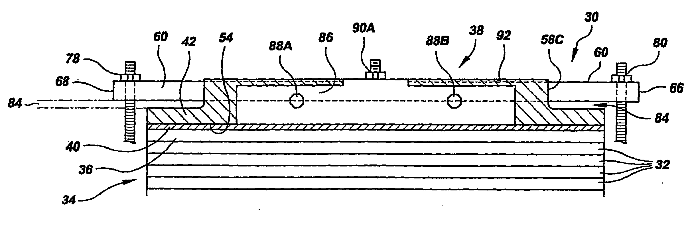
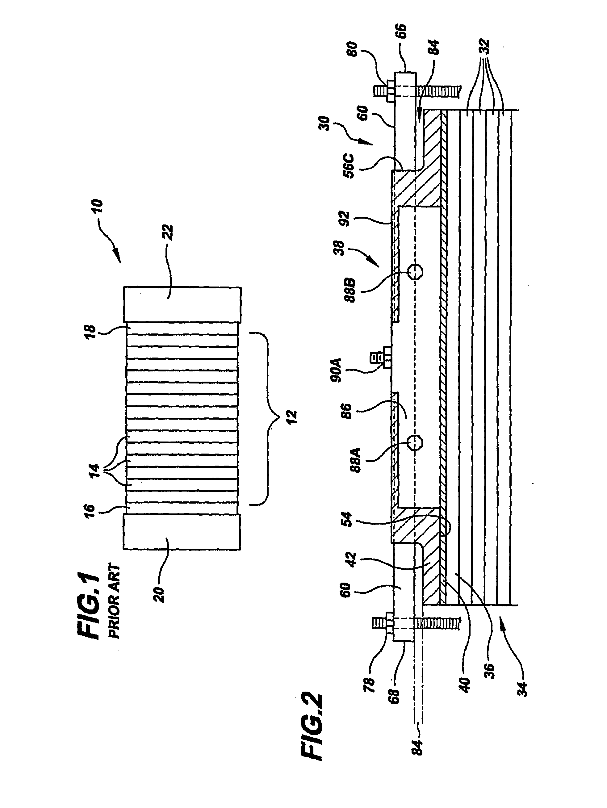
[0021]Referring to the drawings in detail, a sectional view of a fuel cell stack having an integrated end plate assembly is shown in FIG. 2, and is generally designated by the reference numeral 30. The fuel cell stack 30 includes a plurality of fuel cells 32 stacked adjacent each other to form a reaction portion 34 of the fuel cell stack 30 for producing electricity from reducing fluid and process oxidant reactant streams. An end cell 36 is secured at an outer end of the reaction portion 34 of the fuel cell stack 30. The fuel cell stack 30 also includes an integrated end plate assembly 38 secured adjacent the end cell 36.

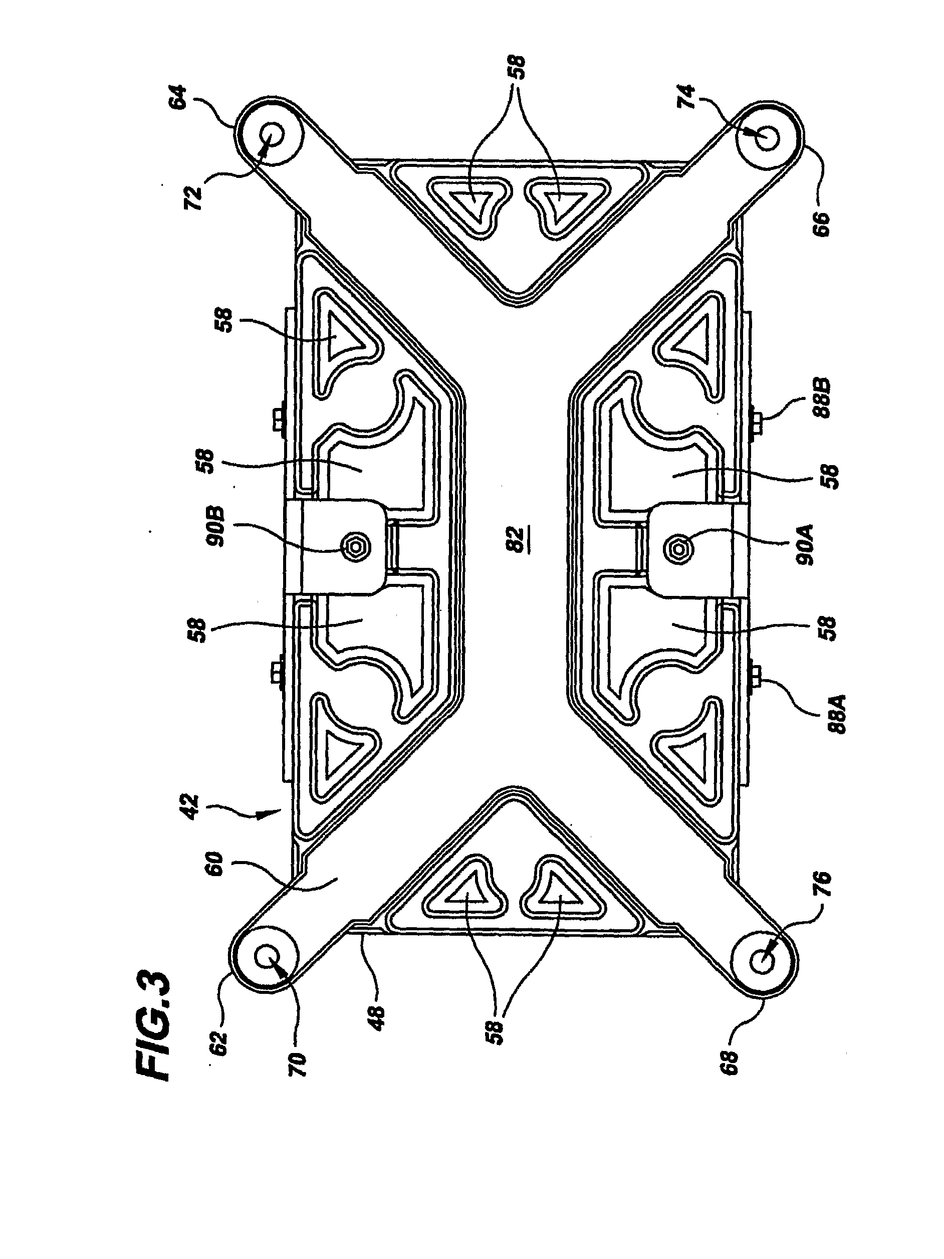
[0022]The integrated end plate assembly 38 includes an electrically conductive current collector 40 secured adjacent to and in electrical communication with the end cell 36 to direct flow of the electrical current from the fuel cells 32, 36 out of the stack 30. A pressure plate 42 is secured adjacent the current collector 40 at a surface of the current collector 40 ...


PUM


Abstract

A fuel cell stack (30) includes an integrated end plate assembly having a current collector (40) secured adjacent and end cell (36) of the stack, a pressure plate (42) secured adjacent the current collector (40), and a backbone (60) secured within a backbone-support plane (44) defined within the plate (42). Tie rod ends (62, 64, 66, 68) of the backbone (60) extend over a gap (84) defined between the backbone-support plane (44) and a deflection plane (50) defined within the pressure plate (42) so that the tie rod ends deflect within the gap (84) upon tightening of tie rods (78, 80). Deflection of the backbone enables the backbone (60) to permit limited expansion of the fuel cell stack (30) during operation, and the backbone (60) has adequate flexural strength to prohibit expansion of the stack (30) beyond operating dynamic limits of the stack (30).

Description

TECHNICAL FIELD[0001]The present disclosure relates to fuel cells that are suited for usage in transportation vehicles, portable power plants, or as stationary power plants, and the disclosure especially relates to a fuel cell stack having an integrated end plate assembly that has a low thermal capacity through use of a combination of a current collector, a light pressure plate and a rigid backbone overlying the pressure plate.BACKGROUND ART[0002]Fuel cells are well-known and are commonly used to produce electrical energy from reducing and oxidizing reactant fluids to power electrical apparatus, such as apparatus on-board space vehicles, transportation vehicles, or as on-site generators for buildings. A plurality of planar fuel cells are typically arranged into a cell stack surrounded by an electrically insulating frame structure that defines manifolds for directing flow of reducing, oxidant, coolant and product fluids as part of a fuel cell power plant. Each individual fuel cell ge...

Claims


Application Information

Patent Timeline
IPC IPC(8): H01M8/24
CPCH01M8/248Y02E60/50H01M8/02H01M8/04H01M8/24
Inventor LAKE, JEFFREY G.BACH, LEONARD A.INIGO, PEDROREGE, EVAN C.VARGAS, CHRISVICTOR, STEPHEN P.
Owner AUDI AG
Why Eureka
Try Eureka