Controllable stiffness catherer guide device

Inactive Publication Date: 2010-06-15
VON WEYMARN SCHARLI ALEXANDER
View PDF13 Cites 18 Cited by
  • Summary
  • Abstract
  • Description
  • Claims
  • Application Information

AI Technical Summary

Benefits of technology

[0016]In accordance with the invention, the control device is finished in such a way that magnetic fields of different polarities can be generated along the first wire thread and along the second wire thread to cause mutual attraction of the wire threads at will. This has the advantage that the individual threads and thereby the guide device is extremely flexible on the whole as long as no magnetic field is generated while the guide device on the other hand is adequately stiff through the mutual attraction of the threads when the magnetic fields are generated. In this way, the guide device in accordance with the invention is adequately flexible on the one hand, for example, for the introduction of the device into a body duct and on the other hand adequately stiff when sliding the catheter along it afterwards, in particular in the area of a branch of the vessel, so that the danger that the guide device can slip out of the intended vessel is extensively excluded. Such a guide device therefore combines two rather contradictory characteristics, namely adequate flexibility on the one hand and adequate stiffness on the other hand, depending upon which characteristic is desired precisely during the handling of the guide device.
[0017]It is an advantage if the first wire thread and / or the second wire thread is made of a magnetizable material, especially from a weakly magnetizable material. It is possible through this to build up the magnetic fields as desired and also to be able to reduce them again depending upon the flexibility or stiffness which is necessary for the guide device in the practical application. In accordance with another further design of the invention, the first wire thread and / or the second wire thread is made of a non-magnetizable material and provided with a magnetizable coating, through which every individual wire thread can be manufactured from a variety of materials to be selected. It is accordingly not necessary to manufacture the entire wire thread out of magnetizable material. It can rather be adequate to provide only the outer jacket of a wire thread with a magnetizable coating so that such a wire thread is also magnetizable.

Problems solved by technology

Furthermore, there is the danger that the forward part of the guide wire can slip out of the intended vessel at a branch of the vessel when inserting a relatively rigid therapy catheter without the use of a guide catheter.

Method used


Image

  • Controllable stiffness catherer guide device
  • Controllable stiffness catherer guide device
  • Controllable stiffness catherer guide device

Examples


Embodiment Construction

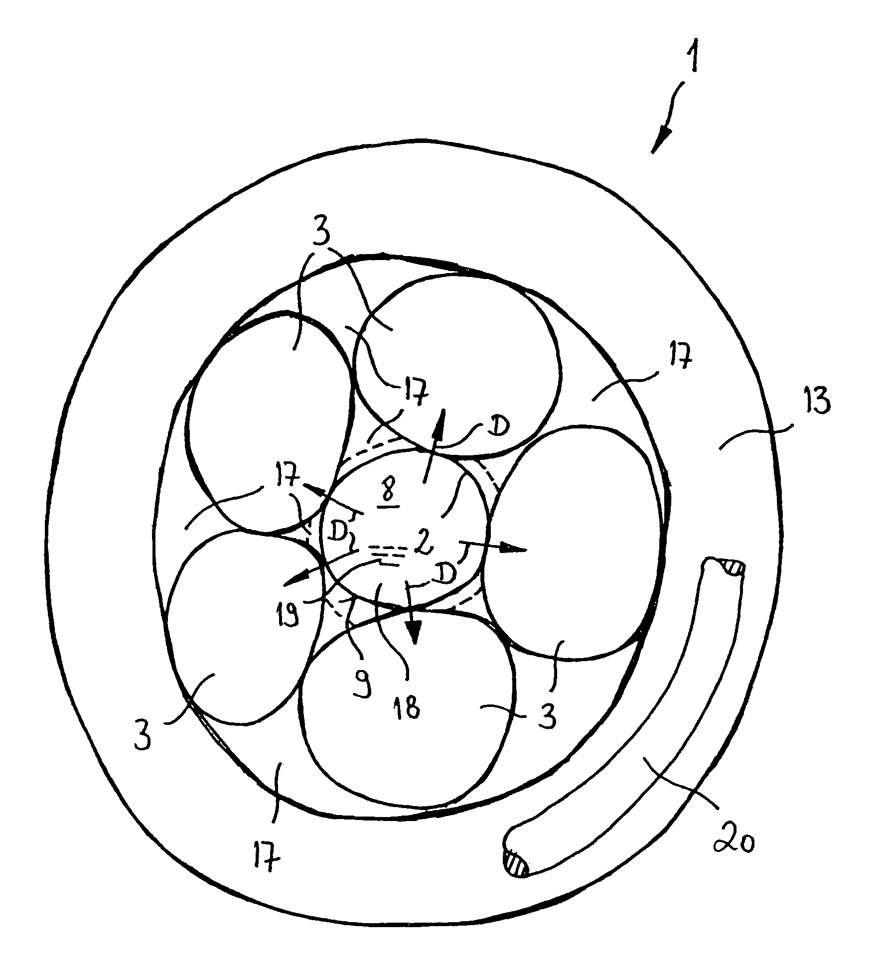
[0036]At first, it is to be noted that the shading symbolizing a cross-section has been omitted in FIG. 1 for better overview.

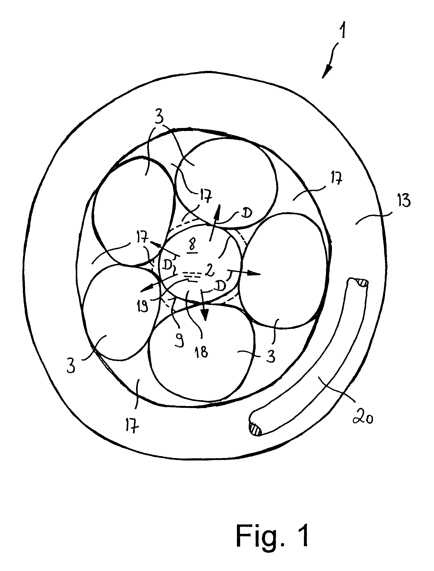
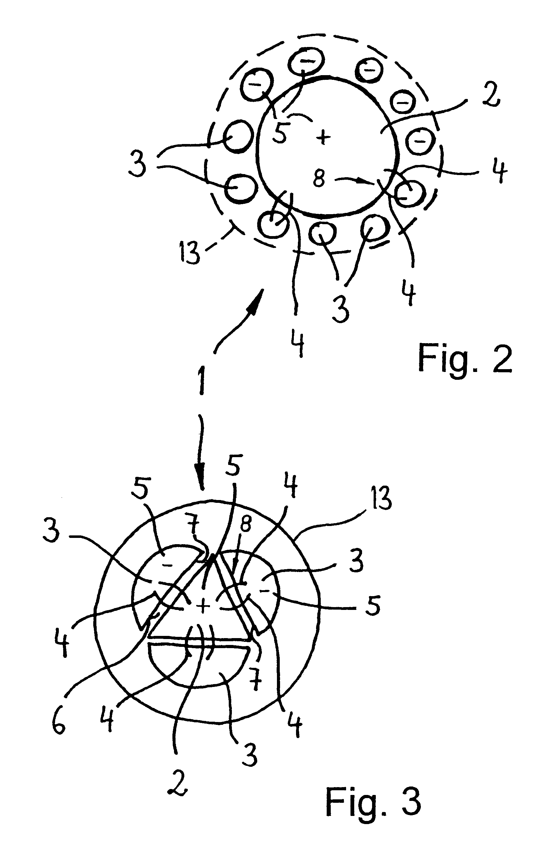
[0037]A schematic cross-section of a guide device 1 is shown in FIG. 1. The guide device 1 is finished in accordance with a form of implementation not belonging to the scope of the invention. The guide device 1 has one first thread 2 in the form of an elongate hollow body, such as a central hose or balloon in accordance with this form of implementation. It is manufactured from a stretchable, elastic material and closely surrounded on its outer circumferential surface 9 by several second threads 3 in the form of elongate bodies made of wire while leaving a spiral cavity 17. There are five second threads 3 arranged in side-by-side relation with one another around the outside circumferential surface 9 of the first thread 2 in the form of implementation shown in FIG. 1. The second threads 3 are surrounded closely by an outer flexible sleeve 13 which is preferably...


PUM


Abstract

A guide device for guiding a therapy catheter in a body duct has a flexible sleeve that is dimensioned to be inserted into the body duct. A first elongate body and one or more second elongate bodies are disposed inside the sleeve in side-by-side relation and extend lengthwise along the sleeve. Magnetic attraction and repulsion forces are selectively created between the first body and the one or more second bodies to vary the stiffness of the guide device. In an alternative arrangement, the first elongate body is a stretchable hollow body and plural second elongate bodies are disposed inside the sleeve around the outer circumference of the first body, the first and second bodies being movable relative to one another to impart flexibility to the guide device. The first body is stretched radially outwardly by introducing pressurized fluid inside the first hollow body to radially press the second bodies against the inner wall of the sleeve to impart stiffness to the guide device.

Description

CROSS REFERENCE TO RELATED APPLICATIONS[0001]The present application is a U.S. national stage application of copending International Application No. PCT / CH2003 / 000556, filed Aug. 19, 2003, claiming priority of Swiss Appln. Nos. 1712 / 02 filed Oct. 15, 2002 and 1083 / 03 filed Jun. 20, 2003, and published in the English language.BACKGROUND OF THE INVENTION[0002]The invention relates to a guide device in particular for the positioning of catheters in a body duct.[0003]The problem is addressed in WO 02 / 34324 A2, in which guide wires connect a section made of a superelastic material with a section made of steel which is significantly stiffer than the first-mentioned section. The guide wire known from WO 00 / 40288 A1 has a shapable body on its distal section, the flexibility of which is changed continuously and should retain its shapable characteristics.[0004]The problem that the guide wire tends to be moved during the withdrawal of the catheter is addressed in EP 0 714 315 B1. The guide wir...

Claims


Application Information

Patent Timeline
IPC IPC(8): A61M25/00A61M25/01
CPCA61M25/0105A61M25/0127A61M2025/0063A61M25/0158A61M25/0155A61M2025/0915
Inventor VON WEYMARN-SCHARLI, ALEXANDER
Owner VON WEYMARN SCHARLI ALEXANDER
Why Eureka
Try Eureka