Engine Control Device, And Its Control Method

a technology of engine control and control device, which is applied in the direction of electric control, machines/engines, mechanical equipment, etc., can solve the problems of high idling rotation to rated rotation not being an efficient field in terms of fuel economy, and the fuel economy cannot be enhanced, so as to improve the operation speed of the operating machine, improve the fuel economy, and reduce the amount of engine fuel consumed.

Active Publication Date: 2010-07-01
KOMATSU LTD
View PDF10 Cites 23 Cited by
  • Summary
  • Abstract
  • Description
  • Claims
  • Application Information

AI Technical Summary

Benefits of technology

[0035]According to the present invention, the first target engine speed is set in accordance with a command value commanded by command means, and the second target engine speed can be set on the side of the low rotation field based on the set first target engine speed. When the engine is to be controlled in a state where the engine output torque is low, the engine can be controlled based on the second target engine speed. With this, the engine can be shifted to a field having excellent fuel economy and can be used without substantially changing the operation performance in the utility vehicle, and the amount of fuel consumed of the engine can be reduced.
[0036]If a pump displacement detected by pump displacement detecting means increases and exceeds a first predetermined pump displacement when the engine is controlled based on the second target engine speed, the target engine speed of the engine can be changed from the second target engine speed to the third target engine speed which is higher than the second target engine speed and is equal to or smaller than the first target engine speed to increase the operation speed of the operating machine, and the engine can be controlled.
[0037]With this, the engine can be rotationally driven in the optimal state in accordance with an operation status of the operating machine required by an operator, and a variable displacement hydraulic pump can absorb maximum output in the engine which is rotationally driven in its optimal state and can discharge pressure oil. Thus, in an operation requiring the maxim

Problems solved by technology

Therefore, a high-speed control field which is determined between no-load high idling rotation to rated rotation is not an efficient field in terms of fuel economy.
When the operation mode switching system as described above is used, however, the fuel economy cannot be enhanced if an operator operates the mode

Method used


Image

  • Engine Control Device, And Its Control Method
  • Engine Control Device, And Its Control Method
  • Engine Control Device, And Its Control Method

Examples


embodiments

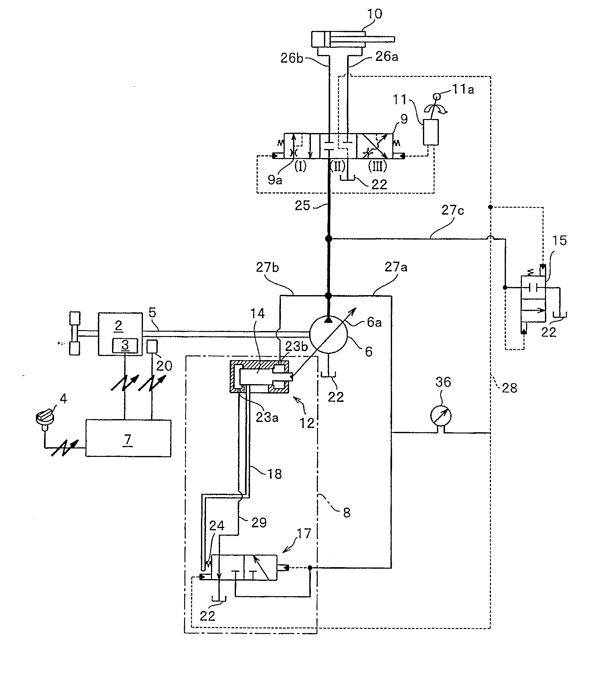
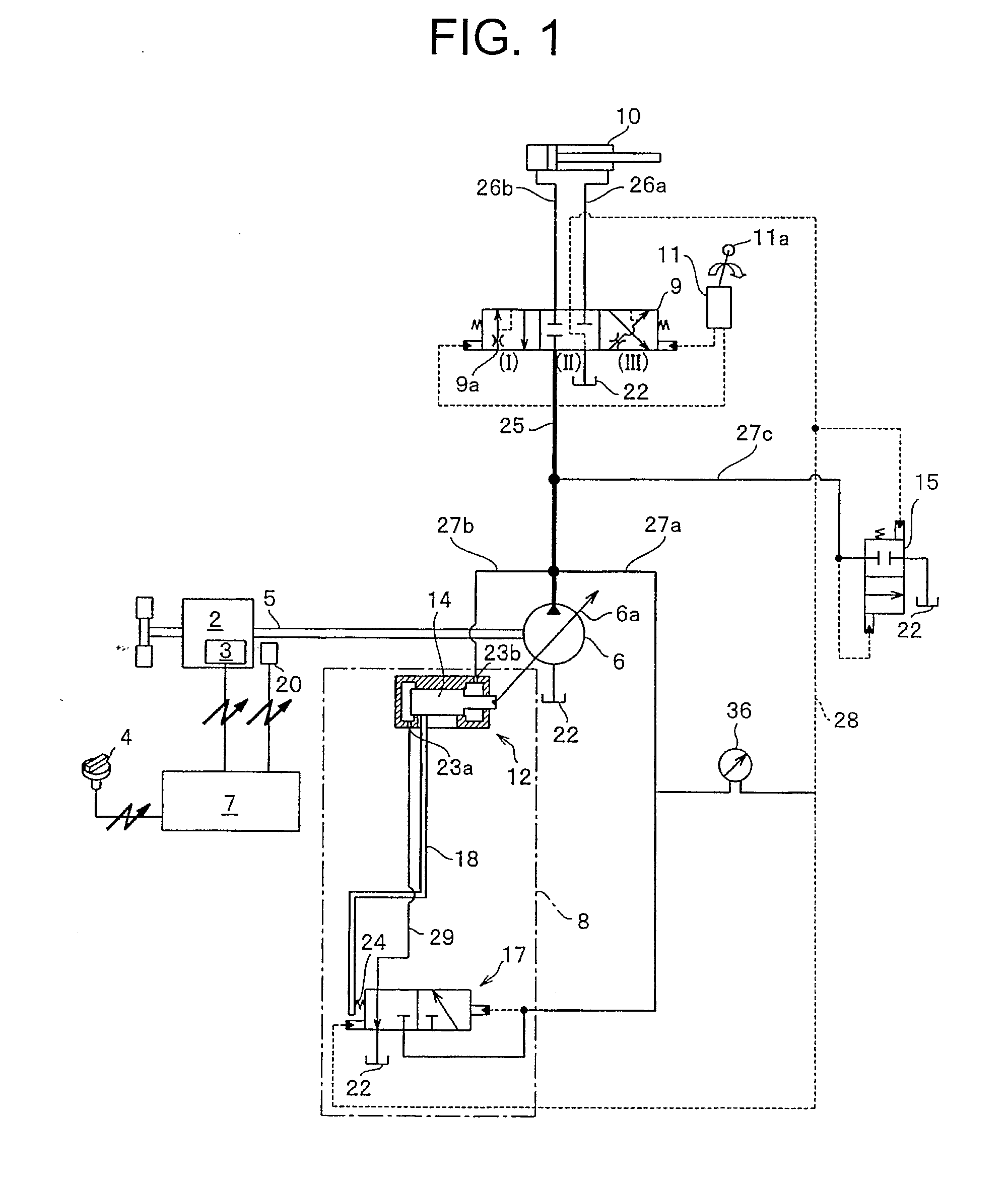
[0102]FIG. 1 is a hydraulic circuit diagram of an engine control device and an engine control method according to an embodiment of the invention. An engine 2 is a diesel engine, and an output torque of the engine is controlled by adjusting an amount of fuel injected into a cylinder of the engine 2. The fuel can be adjusted by a conventionally known fuel injector 3.

[0103]A variable displacement hydraulic pump 6 (hydraulic pump 6, hereinafter) is connected to an output shaft 5 of the engine 2. The hydraulic pump 6 is driven when the output shaft 5 rotates. An inclination angle of a swash plate 6a of the hydraulic pump 6 is controlled by a pump control device 8, and a pump displacement D (cc / rev) of the hydraulic pump 6 is varied by changing an inclination angle of the swash plate 6a.

[0104]The pump control device 8 includes a servo cylinder 12 which controls the inclination angle of the swash plate 6a, and a LS valve (load sensing valve) 17 controlled in accordance with a differential...


PUM


Abstract

A first target engine speed Nh and a high-speed control field F1 are set in accordance with a command value by command means. A second target engine speed N2 on the low rotation side and a high-speed control field F2 are set based on the first target engine speed Nh. When a matching point between an engine load and an engine output torque exceeds a first set position A which is a first predetermined pump displacement during control of an engine in the high-speed control field F2, the high-speed control field F2 is shifted toward the high-speed control field F1. Using, as a new high-speed control field, a high-speed control field 3 in which a differential pressure between a pump discharge pressure and a load pressure of an actuator satisfies a load sensing differential pressure in a pump control device 8, the engine is controlled in the high-speed control field 3, and when the differential pressure does not satisfies the load sensing differential pressure, the speed control field is shifted to the high-speed control field F1. With this, it is possible to provide an engine control device and a control method thereof in which the fuel economy of the engine is enhanced, and when the maximum speed of an operating machine is required, the required maximum speed of the operating machine is not lowered.

Description

TECHNICAL FIELD[0001]The present invention relates to an engine control device and its control method for controlling an engine based on a set target engine speed of the engine, and more particularly to a control device and a control method of an engine for enhancing the amount of fuel consumed of an engine.BACKGROUND ART[0002]In a utility vehicle, when an engine load is engine rated torque or less, the torque is matched with an engine output torque in a high-speed control field in a torque diagram. For example, target engine speed is set in correspondence with setting of a fuel dial, and a high-speed control field corresponding to the set target engine speed is determined.[0003]Alternatively, a high-speed control field is determined in correspondence with the setting in the fuel dial, and the target engine speed of the engine is set in accordance with the determined high-speed control field. Then, control for matching the engine load and the engine output torque is performed in the...

Claims


Application Information

Patent Timeline
IPC IPC(8): F16H61/462
CPCE02F9/20E02F9/2246E02F9/2296F02D29/04F02D41/0205F02D41/021F02D41/083F02D41/2422F15B2211/20553F15B2211/253F15B2211/50536Y10T477/636F02D29/00F02D41/04F02D41/02
Inventor AKIYAMA, TERUOASADA, HISASHI
Owner KOMATSU LTD
Why Eureka
Try Eureka