
Crank mechanism and bicycle incorporating same

a crank mechanism and crankshaft technology, applied in the field of crank mechanisms, can solve the problems of increasing wind resistance during coasting periods, requiring a certain amount of skill, and unable to provide a way for a user to drive the crankshaft, so as to reduce aerodynamic drag

Inactive Publication Date: 2010-07-01
DAY FRLIN J
View PDF84 Cites 12 Cited by
  • Summary
  • Abstract
  • Description
  • Claims
  • Application Information

AI Technical Summary

Benefits of technology

[0009]In a bicycle equipped with one embodiment of the crank mechanism disclosed herein both of a pair of crank arms can be placed in a raised position extending steeply upward so that their respective pedals are both near an uppermost position of rotation, while the crank arms urge the crankshaft in opposite directions, so that the cyclist can rest with both knees raised, to provide a reduced aerodynamic drag (similar to a ski racing tuck) while the bicycle is coasting.

Problems solved by technology

Once the crank arms are allowed to move away from the usual 180 degree opposite orientation, regaining the desired relative positions may be awkward and requires a certain amount of skill.
The unidirectional clutches in the arrangement disclosed in U.S. Pat. No. 5,860,329 are somewhat costly, and they do not provide a way for a user to drive the crankshaft in an opposite direction of rotation and, when used during racing they offer the further disadvantage of increasing wind resistance during coasting periods because a bicycle equipped with such a crank mechanism does not provide for coasting with a cyclist's feet in the conventional forward and rearward opposite positions at crankshaft height.

Method used


Image

  • Crank mechanism and bicycle incorporating same
  • Crank mechanism and bicycle incorporating same
  • Crank mechanism and bicycle incorporating same

Examples


Embodiment Construction

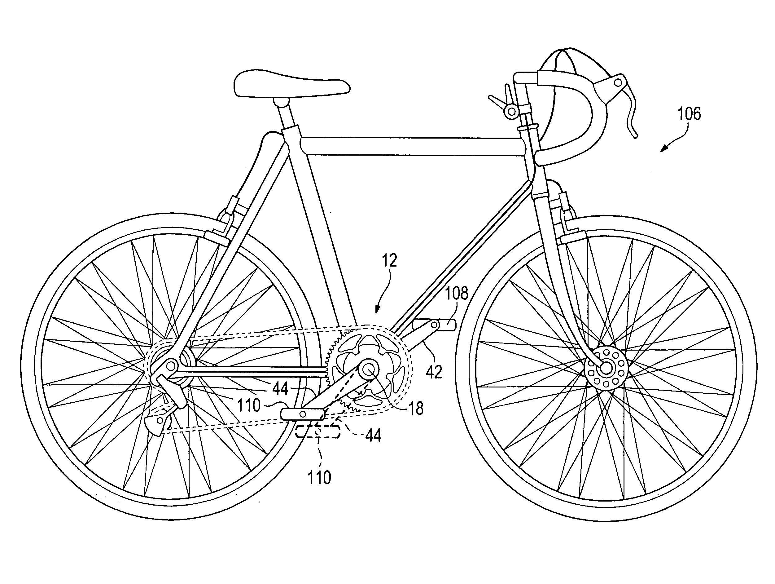
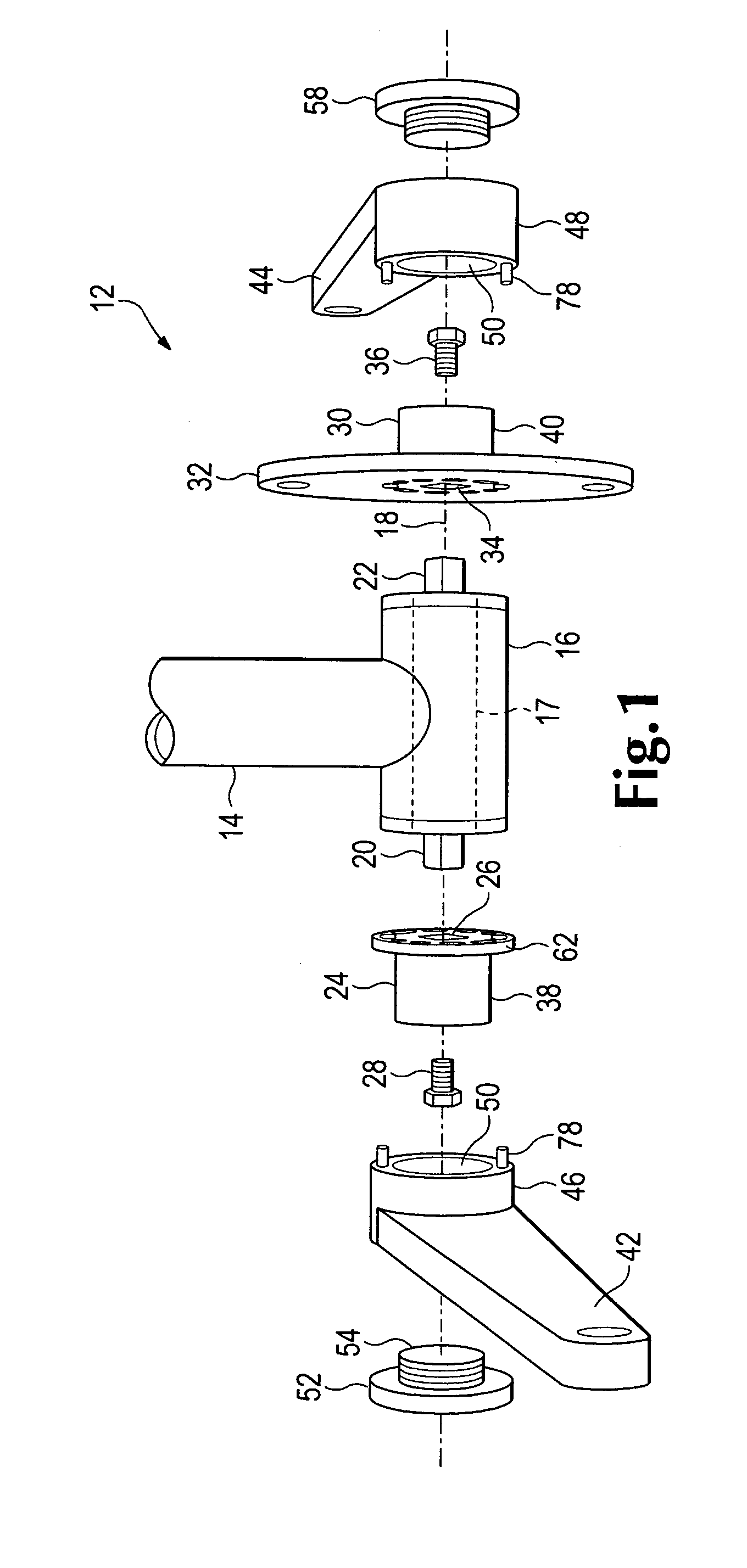
[0028]Referring now to the drawings which form a part of the disclosure herein, a crank mechanism 12 is shown in an exploded perspective view, together with part of a seat tube 14 of a conventional bicycle frame and a bottom bracket 16 in which a conventional crankshaft 17 is supported in suitable bearings for rotation about an axis of rotation 18. The crankshaft 17 shown herein has conventional tapered square ends 20 and 22 as used to receive and be driven by a pair of crank arms in a conventional bicycle.

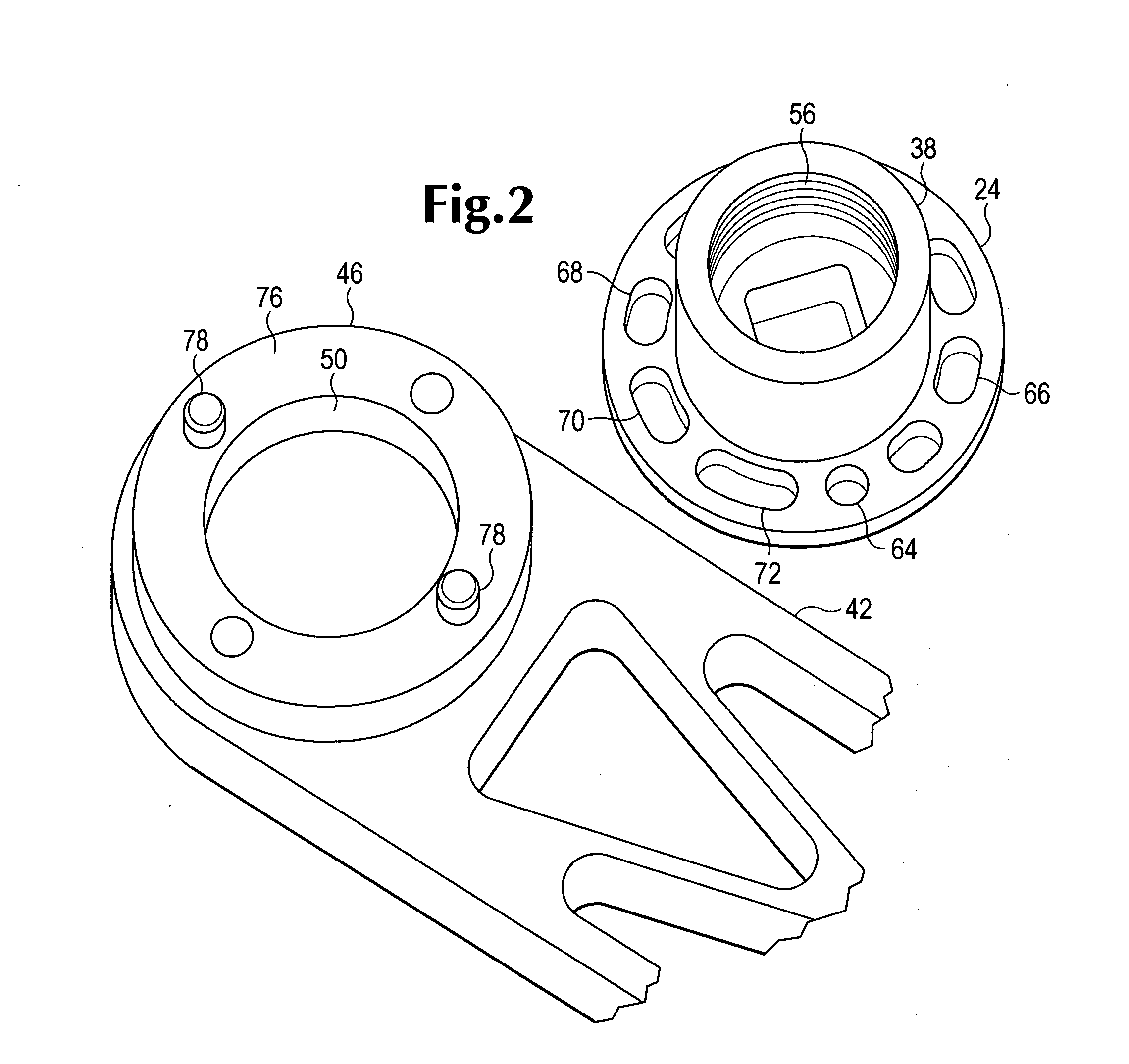
[0029]In the crank mechanism 12 as shown here, a drive adaptor 24 defines a square hole 26 that fits on the square end 20 of the crankshaft 17, and a bolt 28 extends through the drive adaptor 24 into a threaded bore within the square end 20 to fasten the drive adaptor 24 to the square end 20 in a manner similar to that used to attach a conventional bicycle pedal crank arm to a crankshaft.

[0030]Similarly, a drive adaptor 30 that includes a chain ring receiving flange 32 defines a c...


PUM


Abstract

A crank mechanism useful on a bicycle or an exercise machine utilizing a pair of crank arms. A crank arm is attached to a crankshaft so that it can turn the crankshaft in either direction but is free to move through a defined angle about the crankshaft between positions of oppositely driving engagement with the crankshaft. The mechanism can be used in training athletes. In one embodiment the mechanism can be used to aid a bicyclist in maintaining an aerodynamic posture.

Description

CROSS REFERENCE TO RELATED APPLICATION[0001]This application claims the benefit of U.S. Provisional Patent Application Ser. No. 61 / 204,216, filed Dec. 31, 2008.BACKGROUND OF THE INVENTION[0002]The present disclosure relates to crank mechanisms and more particularly to crank mechanisms useful in bicycle drives and in exercise machines and to use of such mechanisms in racing and in strength and coordination training for athletes.[0003]The present applicant's U.S. Pat. No. 5,860,329 discloses a crank system in which a clutch is associated with each of a pair of pedal cranks. A user's feet must be clipped or otherwise connected to the pedals and the user must pull each pedal up, constantly keeping each crank arm urging the crankshaft forward, in order to keep the pedals from departing from a normal 180 degree crank arm separation angle. Once the crank arms are allowed to move away from the usual 180 degree opposite orientation, regaining the desired relative positions may be awkward and...

Claims


Application Information

Patent Timeline
Patent Type & Authority Applications(United States)
IPC IPC(8): A63B22/06B62M3/00
CPCB62M1/36B62M3/00Y10T74/2164
Inventor DAY, FRANKLIN J.
Owner DAY FRLIN J
Learn More