
Autonomous Power Supply System

a power supply system and autonomous technology, applied in the direction of electric generator control, wind motor with solar radiation, machines/engines, etc., can solve the problems of loss reduction, and achieve the effect of expanding the wind range and increasing the operational effectiveness

Inactive Publication Date: 2010-07-08
IP REACT +1
View PDF4 Cites 23 Cited by
  • Summary
  • Abstract
  • Description
  • Claims
  • Application Information

AI Technical Summary

Benefits of technology

[0012]The base task of the present invention is to create the system of independent energy supply providing increase of its operational effectiveness by means of losses for electric current conversion decrease and within the expanded wind range of the wind generator setup.
[0018]At strong winds such device will permit to lower a wind load on the rotor blades and the tower, and will provide monitoring of maximal power delivered by the generator. That will provide not only for the optimal mode of the generator operation resulting in its life time prolongation, but also will decrease the risk of damage.
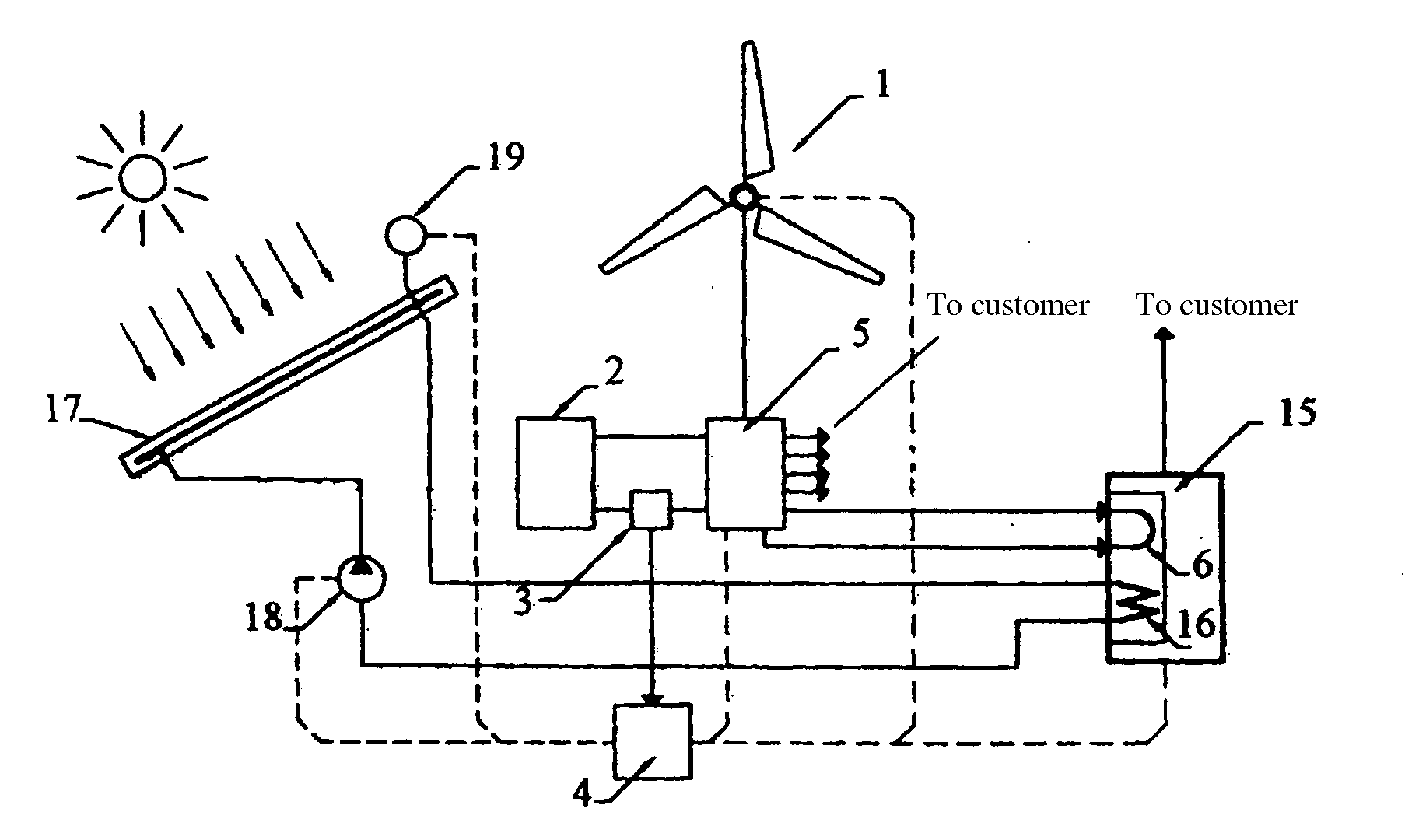
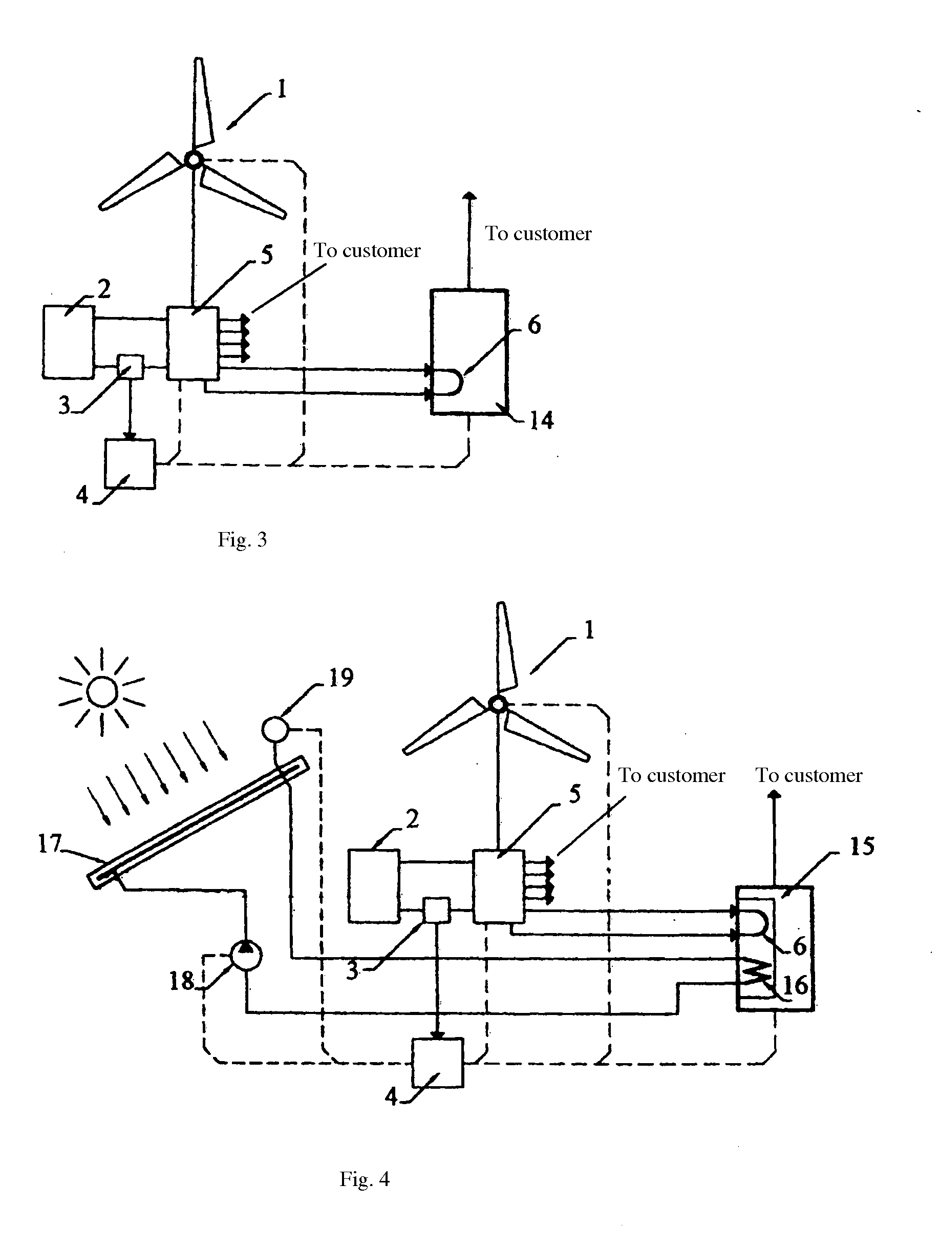
[0019]When the Independent energy supply system is operating in the conditions of hot climate, when the main power inputs fall on the cooling system, it is expediently to use the absorption cooling machine (ACM), and the heat produced by a resistive load of the stabilization system for rotor speed of the wind generator is to supply directly to the generator's ACM. It contributes to operation efficiency of all the systems of energy supply in the whole.

Problems solved by technology

By that, the necessity of electric energy conversion to gain required power grid parameters is excluded, what results in loss decrease.

Method used


Image

  • Autonomous Power Supply System
  • Autonomous Power Supply System
  • Autonomous Power Supply System

Examples


Embodiment Construction

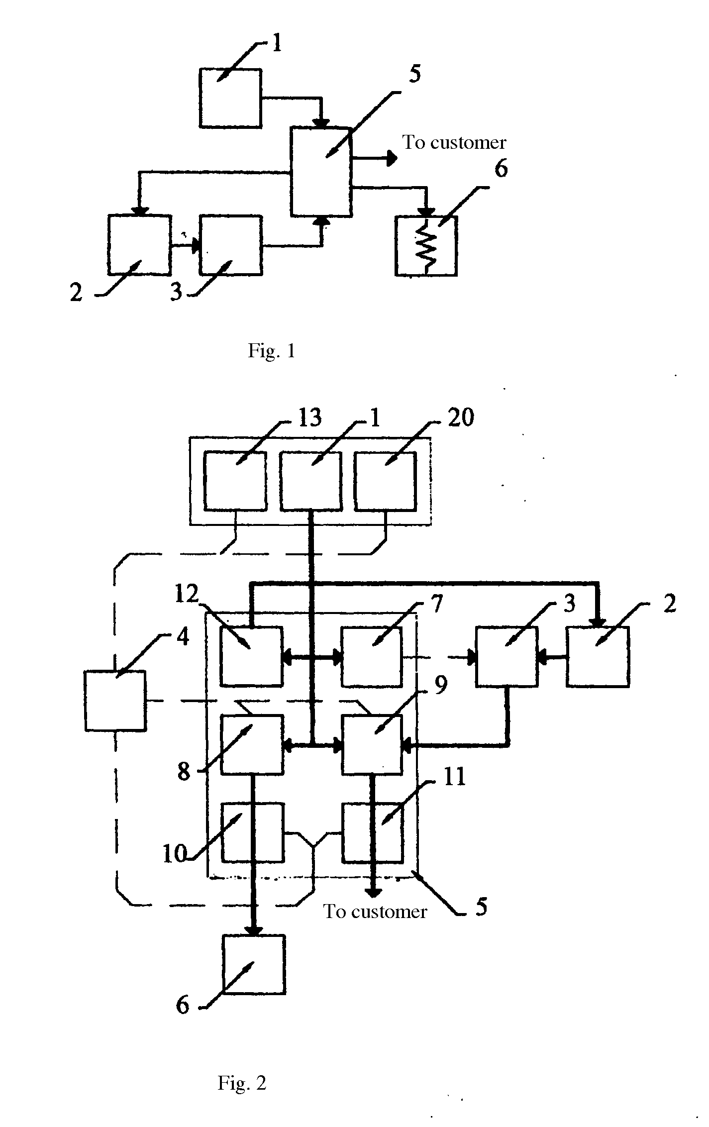
[0027]As it shown in FIG. 1, the energy supply system IES contains wind generator setup 1 and electric storage battery 2 with inverter 3. IES has an automatic control system (ACS) 4, connected through heat and electric loads sensors with actuating mechanisms. Wind generator 1 and electric storage battery 2 with inverter 3 are electrically bound with network regulator 5. Resistive load 6 is electrically bound through network regulator 5 with wind generator 1. The resistive load 6 is a system of thermal electric heaters (TEHs), here the power dissipated on them is dependent on wind generator operation and on power consumers.

[0028]Network regulator 5 (FIG. 2) contains synchronizer 7, control unit for resistive load 8, switchboard 9 and, correspondingly, sensor for resistive load current, and wind generator sensor 10, 11 and charger 12.

[0029]A wind generator 1 is equipped with a pivoting device 13 for wind generator blades to change the angle of attack operated by ACS 4. The blades pivo...


PUM


Abstract

The invention concerns the power systems utilizing renewable power sources, in particular, refers to the systems utilizing wind and solar energy and may be used for the independent power supply both in cold and hot climate. The independent energy supply system (IES) contains a wind generator setup for electric power production and a solar collector. The solar collector is connected with a heat storage. IES also includes an electric energy storage battery, inverter, and automatic control system for IES connected through the heat and electrical load sensors with actuating mechanisms. IES is also equipped with the stabilization system for rotor speed of the wind generator that includes a network regulator with a control unit for a resistive load, electric current sensors and rotor speed sensor. The resistive load is the system of thermal electric heaters (TEHs). The energy dissipated on TENs is to be accumulated in the heat storage. The absorption cooling machine may be included in the IES, and the TEHs may be placed inside its generator. IES contains the device for wind generator blades turning. The heat exchanger of the solar collector is located inside the absorption cooling machine generator.

Description

RELATED APPLICATIONS[0001]This application is a Continuation of International Application No. PCT / RU2007 / 000514 filed on Sep. 14, 2007, which is incorporated herein by reference in its entirety.FIELD OF THE INVENTION[0002]The invention concerns the heat and electric power supply for homes and industrial areas by means of the power systems using renewable power sources.BACKGROUND OF THE INVENTION[0003]In the conditions of permanent deficit and cost increase of the conventional hydrocarbon power sources, a special attention is paid to usage of so called alternative or renewable energy.[0004]The power systems are known that are produced by plants working on ecologically clean renewable power sources (wind, sun, and etc.). Nevertheless, instability of energy flow in the source (change of wind strength, climatic and seasonal variations of light energy flow) creates obstacles in supplying the consumers with quality energy. To improve the power supply stability, the combined systems are de...

Claims


Application Information

Patent Timeline
IPC IPC(8): F25B15/00F24J2/34H02P9/04H02J7/14
CPCF03D9/007F03G6/00Y02E10/465Y02P90/50F03D9/22Y02E10/725F03D9/25F03D9/11Y02E10/46Y02E10/72Y02E70/30
Inventor TSAREV, VIKTOR V.ALEKSEEVICH, ALEXANDER N.
Owner IP REACT
Learn More