Easily mountable and removable universally adjustable traction apparatus for vehicle tires

a technology of universal adjustment and tire mount, which is applied in the direction of vehicle components, non-skid devices, transportation and packaging, etc., can solve the problems of difficult for these folks to find needed parts, high questionable life span of sensitive springs, gear systems and many other sensitive parts, etc., and achieves the effect of easy and quick attachment to a tire moun

Inactive Publication Date: 2010-07-08
POLYAKOVICS FRANK L
View PDF8 Cites 17 Cited by
  • Summary
  • Abstract
  • Description
  • Claims
  • Application Information

AI Technical Summary

Benefits of technology

[0005]To this end, it is an object of the present invention to provide a traction apparatus assembly that may be packaged in a container easily stored in a vehicle and ready for easy assembly and immediate installation on a vehicle tire when the need arises and which can be as easily and quickly removed from the tire when it is no longer needed.
[0007]A still further object of the invention is the provision of a vehicle tire traction apparatus that may be easily and quickly attached to a tire mounted on a wheel without the need to mount the apparatus directly to the wheel on which the tire is mounted.

Problems solved by technology

However there are some common weaknesses that appear in most of these devices, for example: sensitive springs, gear systems and many other sensitive parts.
The life spans of these parts are highly questionable under brutal conditions like snow mixed with salt, sand and mud, which is the reality of winter driving.
There are thousands of small towns located far from big cities that would make it difficult for these folks to find needed parts in the middle of a winter storm season.
What would happen if the parts were not available is that while most of the prior art devices claim to be very simple, a close examination reveals just the opposite of that, resulting in the inability to repair the prior art devices.
Many of these prior art devices have simple working procedures but they are made of expensive and difficult to reproduce parts that only the original manufacturer could easily reproduce some of these complicated parts.
For example, especially formed parts with machine-cut gear teeth in them, or gears with square holes in their centers; springs that are made to specifications; or parts injection molded and not easily replaceable.
There are many other small parts in the prior art devices that are very costly or impossible to reproduce in small shops.
But it would be difficult to imagine a more effective way to cut through stubborn ice that is frozen to the surface of the roadway than to use the abutting sharp edge of an inverted 90° angle “V” bar claw.
While the double back side edges of the “V” bar claw grab the rubber on the tire, some portion of these back side edges extend into the recesses between treads of the tire, which then make it impossible for the inverted “V” bar claws to slip in relation to the tires.
It is questionable how many of the above listed prior art devices could stand up to high-power V-8 engines like 357 Chevy Van or 6.2 or 6.5 V-8 power engines or, for that matter, the many other V-8 trucks and vans traveling ice covered roads all over the country.
Even if it was possible to perfectly balance the wheel with that extra weight it is questionable how long it would stay that way bouncing in pot holes or scraping the curb of sidewalks while parking.
It should be noted that out of balance wheels could damage the treads on tires or, even worse, it could damage the bearings in the wheels.
None of the above listed prior art devices can make such a claim.
U.S. Pat. No. 4,122,880 suggests that by increasing the gripping members, it increases the device's complexity.
It will also increase the time involved in attaching these members to the tire and also adds extra weight to the vehicle's wheels.
No doubt the above devices would do well on paved roads under normal conditions but when heavy snow or ice covers the surface of the road the user may not be able to tell where the pavement ends and the device may be forced to withstand an unpaved narrow frozen road that could test even the most sturdy mechanism.
It also challenges the above listed prior art devices in their life span and practicality to be effective in the function for which they were designed.

Method used


Image

  • Easily mountable and removable universally adjustable traction apparatus for vehicle tires
  • Easily mountable and removable universally adjustable traction apparatus for vehicle tires
  • Easily mountable and removable universally adjustable traction apparatus for vehicle tires

Examples


Embodiment Construction

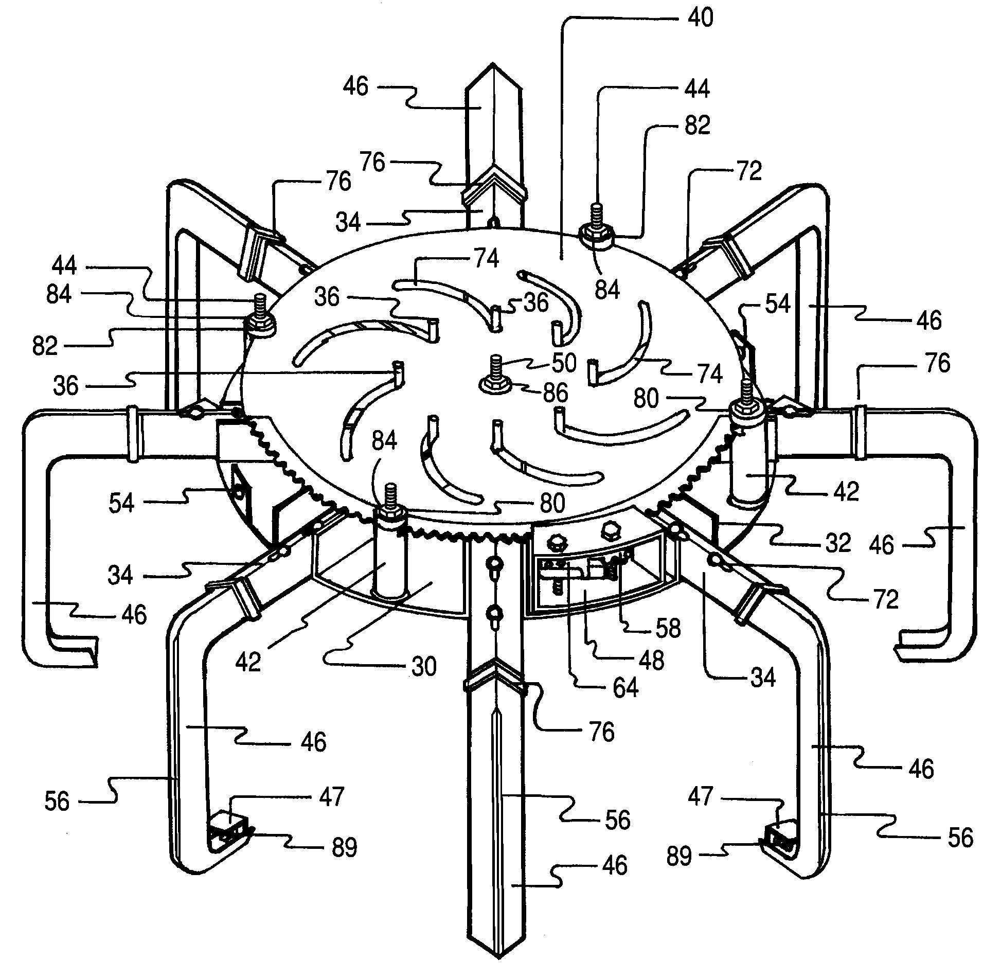
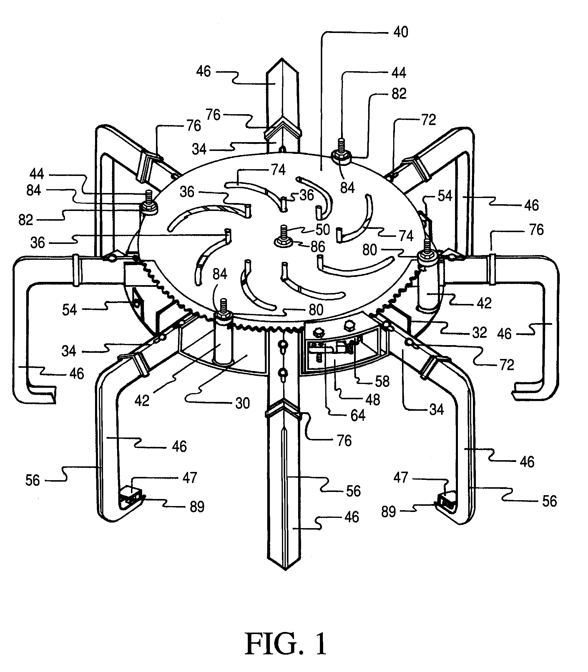
[0036]The purpose of the apparatus shown in the drawings, when applied to the periphery of the driving tires of a vehicle, be it a passenger automobile, a pick-up truck, a flat bed or cargo truck or a bus for passengers, is to provide spaced transverse abutments across the periphery of the tire that dig into the snow, earth or mud when the tire rotates so as to propel the vehicle forward or backward as the need may be. Because of its design, it may easily be applied to the tire and locked in place without exertion of a great deal of force. Generally, the various parts of the apparatus will be referred to herein by appropriate reference numbers also indicated in the drawings.

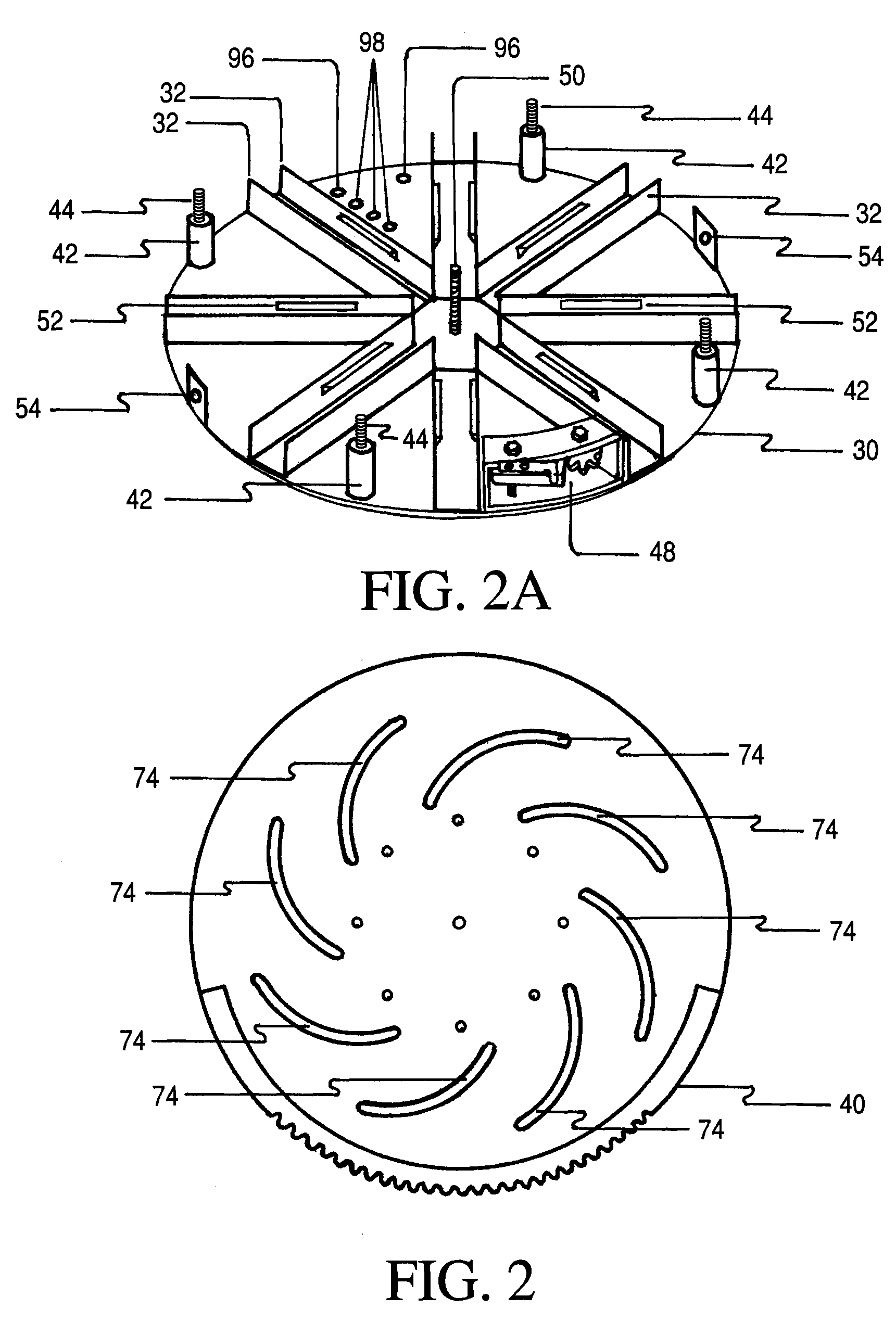
[0037]Referring to the drawings, initially to FIGS. 1, 2 and 2A, steel plate 30 serves as a strong backing plate able to withstand the force imposed by powerful V-8 engines. Metallic channel guides 32 (FIG. 2A) are superimposed on the surface of and welded to backing plate 30 at eight intervals angularly spaced f...


PUM


Abstract

The primary difficulty with equipment applicable to automobile tires to increase traction on snow-covered ground is mounting the equipment to the tire. The subject apparatus includes a base plate having multiple radially extending slots within which are slidably mounted radially extending rods to which are attached tire engaging claw members that overlap the periphery of the tire. A control plate is mounted onto the base plate and a gear mechanism is mounted between the two plates so that the gear mechanism may be operated to draw the claws inwardly to impose a retention pressure on the periphery of the tire. Means are provided to lock the apparatus in a tire tread engaging position. To remove the apparatus, the locking means are released and the claws are radially extended away from the tire so that the entire assembly may be removed from the tire.

Description

FIELD OF THE INVENTION[0001]This invention relates essentially to a fully assembled apparatus that may easily be attached to vehicle tires without the need of raising the tires off the ground or supporting surface, be it sand, snow or mud.DESCRIPTION OF THE PRIOR ART[0002]Various designs of tires have been produced to augment traction in wet, slushy or snow conditions. Some of these include tread designs alleged to provide added traction. Others include the placement of metal studs in tires to provide added traction, but these stud-equipped tires require tedious removal and replacement by conventional tread tires when road conditions no longer demand stud-equipped tires. Chains have been applied to tires to increase traction, but these are difficult to apply, frequently wear thin and break, and are difficult to remove. Examples of other devices that have been developed to provide added traction are shown in the United States patents listed hereinafter.U.S. Pat. No.Issue DateU.S. Cla...

Claims


Application Information

Patent Timeline
Patent Type & Authority Applications(United States)
IPC IPC(8): B60C27/04
CPCB60C27/04
Inventor POLYAKOVICS, FRANK L.
Owner POLYAKOVICS FRANK L
Why Eureka
Try Eureka