High Precision Belt Weighing Array System for Dispersed Material

a belt and array technology, applied in the field of belt weighing arrays, can solve the problems of multiple support point load cells in the platform that will inevitably interfere with one another, and the problem of long-term reliability is always a major problem

Inactive Publication Date: 2010-07-08
YUAN YANQIANG
View PDF15 Cites 8 Cited by
  • Summary
  • Abstract
  • Description
  • Claims
  • Application Information

AI Technical Summary

Benefits of technology

[0017]Belt tension is caused by conveyor motors driving the belt. Tension force is affected by the flow of material and it is the major source of error for belt weighing units.
[0018]Referring to FIG. 3, a simplified depiction of a belt weigher is shown. In that Figure, the numeral 3′ refers to the fixed roller, numeral 1 refers to the load cell, numeral 3 refers to the weighing roller, numeral 7 refers to the belt and numeral 8 refers to the bulk material carried by the belt. A diagram showing forces acting on each abovedescribed component is presented in FIG. 4 where Fw is the gravitational force of the material, Fc is the gravitational force of the material exerted on the load cell, Fp is the belt tensional force and a is the angle formed by the downward deflection of the weighing roller under the load of the bulk material disposed on the belt. These forces can be expressed in the following formula:
[0022]3. The quality of installation of the belt weigher can also contribute to error in that angle α will be positive if the belt weighing unit is not installed in a perfectly horizontal disposition. In addition, belt tension may change in operation due to factors such as the change in material throughput with the result that the error changes.
[0023]The present invention seeks to ameliorate one or more of the abovementioned disadvantages.
[0024]Therefore, in accordance with one aspect of the present invention, there is provided a bulk material belt weighing unit including: a single point load cell and a weighing frame, the frame including a weight bearing beam; roller brackets and weighing roller assemblies, wherein there are provided at least two roller brackets spaced apart from and generally parallel to each othe

Problems solved by technology

In known belt weighers, neither the structure of the weighing platform or the frame that supports it inhibits deformation caused by external force and fatigue stress, therefore the multiple support point load cells in the platform will inevitab

Method used


Image

  • High Precision Belt Weighing Array System for Dispersed Material
  • High Precision Belt Weighing Array System for Dispersed Material
  • High Precision Belt Weighing Array System for Dispersed Material

Examples


Embodiment Construction

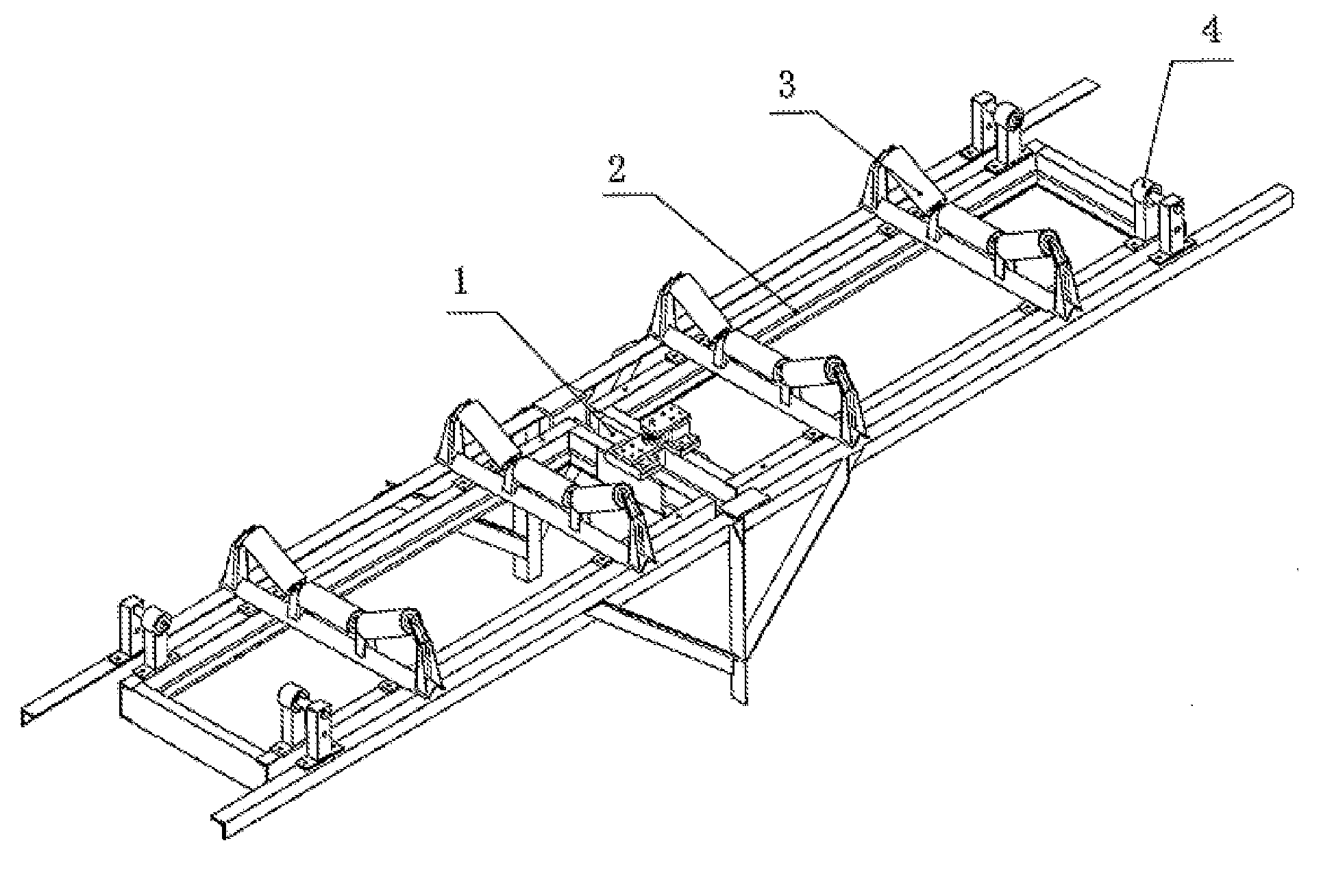
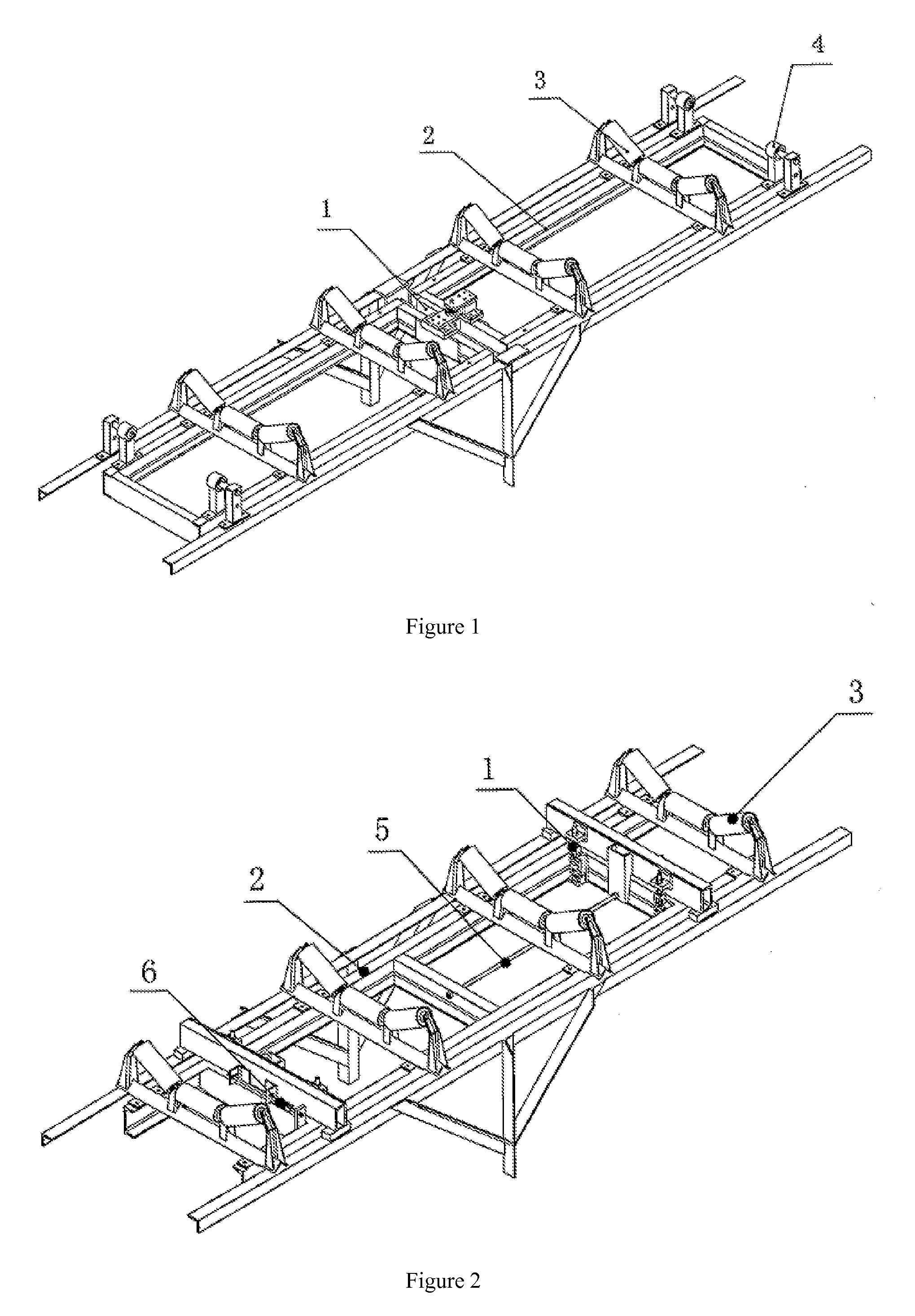
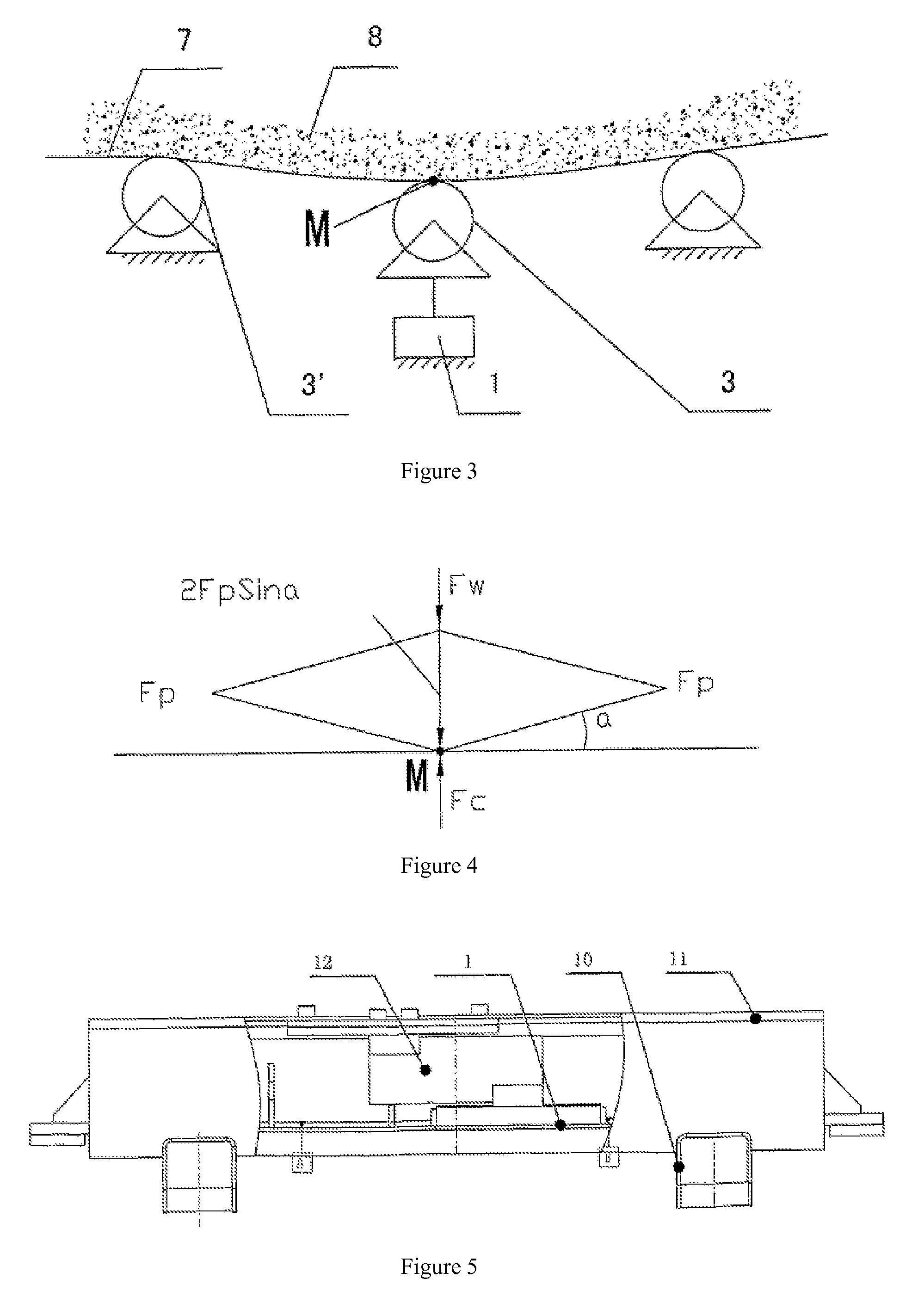
[0055]Referring to FIGS. 5 and 6 there is shown a weighing unit in accordance with a preferred embodiment of the present invention. The weighing unit includes a load cell 12, a weighing frame including a weight-bearing beam 11, roller brackets 10 and weighing rollers 3. In the embodiment shown there are two roller brackets 10, on either side of the load cell and approximately parallel to each other, which use support portions to support the three-part, V-shape weighing roller assemblies 3, disposed at both roller bracket or weighing frame ends respectively. Weight bearing beam 11 in the preferred embodiment shown uses steel sheet that bent in a channel shape, which has a higher bending resisting modulus with relatively light weight than a solid beam. Thus the weight-bearing beam is resistant to sinking under weight, despite its light structure. The channel shape weight-bearing beam has two indentations adjacent to each end that correspond with roller bracket 10. Mid sections of the ...


PUM


Abstract

A belt weighing array system for dispersed material in a transportation process of measurement is mainly composed of a weighing sensor (12), a bearing beam (11), a supporting roller holder (10), and weighing supporting rollers (3). On both ends of the supporting roller holder (10) formed by at least two parallel arms, the weighing supporting rollers (3) are supported respectively, and the middle part of the supporting roller holder (10) is fastened with the bearing beam (11) across both sides, which is connected to a force transfer unit of the weighing sensor (12) fixedly. The sensor belongs to single type weighing sensor, and its base is arranged fixedly on a frame of a belt transporter by both sides.

Description

TECHNICAL FIELD OF THE INVENTION[0001]The present invention relates generally to a weighing apparatus, as well as, in one embodiment, a belt weighing array. Both aspects and embodiments of the present invention measure a mass of bulk material in motion, while the material is disposed on the belt.BACKGROUND TO THE INVENTION[0002]Belt weighers are widely used for measuring a mass of bulk material in motion. It is thought that, at present, approximately 98% of continuous mass measurement of belt-conveyed bulk material is done by belt weighers that use the gravitational measurement principle. Based on the applicant's long period of practice and research in this area, the technological features of known belt weighers are summarized hereinbelow:[0003]1. Known Belt Weighers[0004]Known belt weighers are used to measure the mass of bulk material in motion. Usually, a weighing platform is installed at a certain section of a conveyor belt assembly. That is, a customized belt weigher platform i...

Claims


Application Information

Patent Timeline
IPC IPC(8): G01G11/00
CPCG01G11/04
Inventor YUAN, YANQIANG
Owner YUAN YANQIANG
Why Eureka
Try Eureka