Multi-capillary electrophoresis cartridge interface mechanism

US20100170799A1Inactive Publication Date: 2010-07-08QIAGEN SCIENCES LLC

Image

  • Multi-capillary electrophoresis cartridge interface mechanism
  • Multi-capillary electrophoresis cartridge interface mechanism
  • Multi-capillary electrophoresis cartridge interface mechanism

Examples


Embodiment Construction

[0044]This invention is described below in reference to various embodiments with reference to the figures. While this invention is described in terms of the best mode for achieving this invention's objectives, it will be appreciated by those skilled in the art that variations may be accomplished in view of these teachings without deviating from the spirit or scope of the invention.

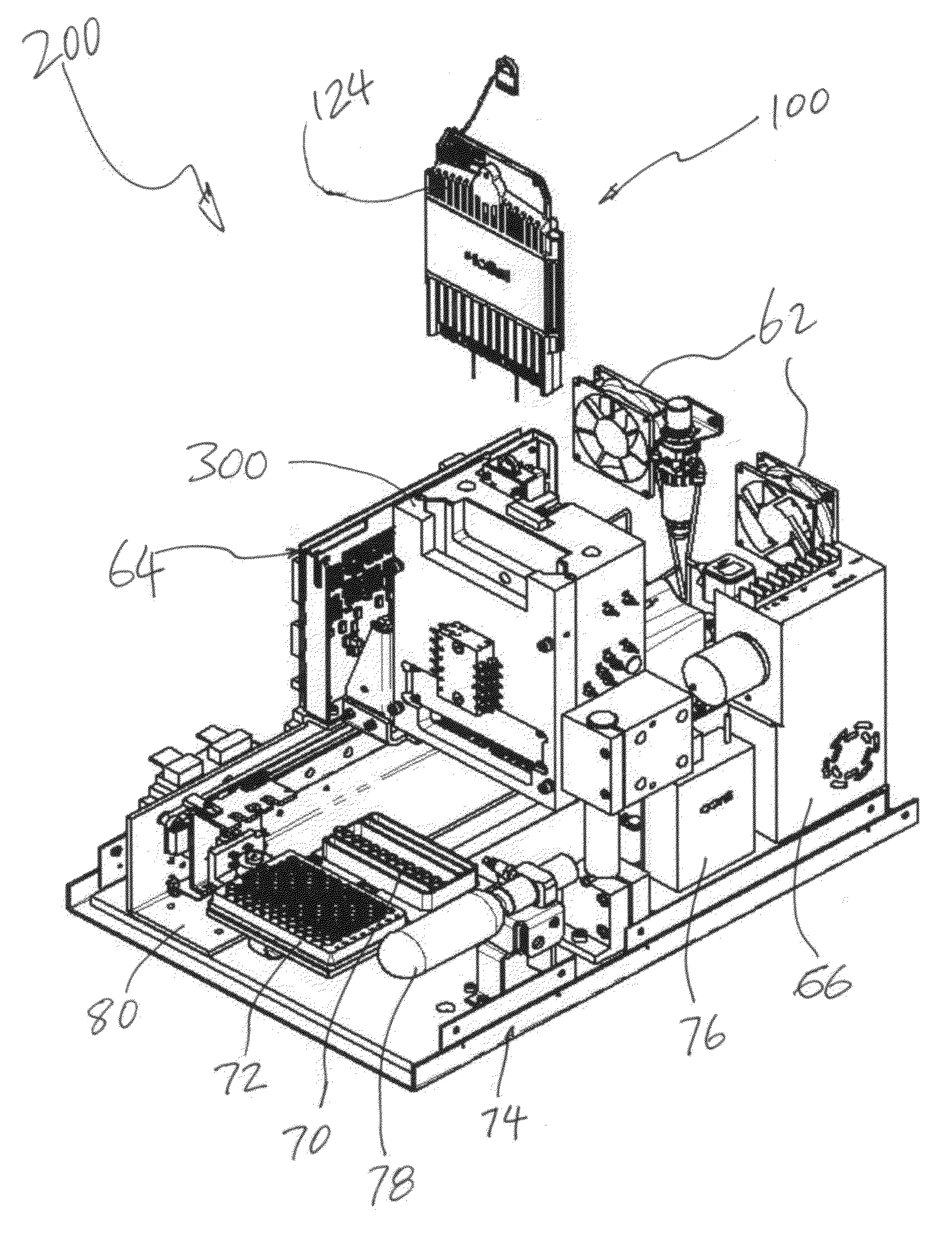
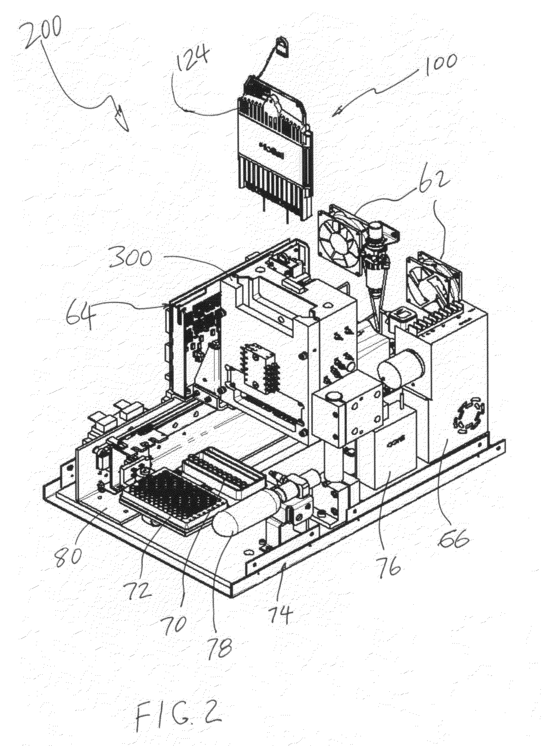
[0045]The present invention provides for an interface mechanism bio-separation instrument that supports a multi-segment cartridge. For purpose of illustrating the principles of the present invention and not by limitation, the present invention is described by reference to embodiments directed to capillary electrophoresis and radiation induced fluorescence.

Overview of CE

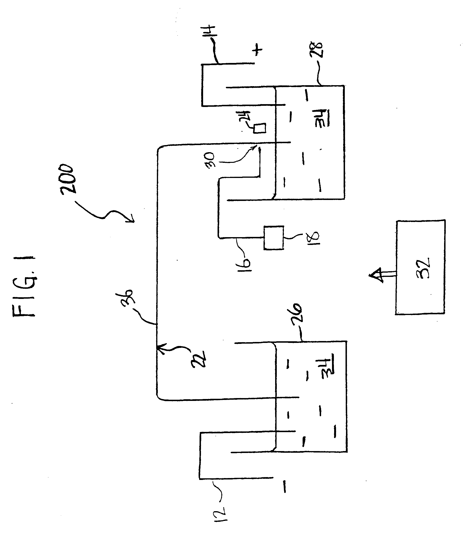
[0046]Referring to FIG. 1, a bio-separation system, more specifically a capillary electrophoresis (CE) system 200 that incorporates the present invention is schematically illustrated. The CE system 200 generally comprises a capillary separat...


PUM


Abstract

The present invention provides for an interface mechanism in a bio-separation instrument that makes interface connections to a multi-channel cartridge. The interface mechanism precisely positions the cartridge in relation to the support elements in the instrument (e.g., high-voltage, gas pressure, incident radiation and detector), and makes automated, reliable and secured alignments and connections between various components in the cartridge and the support elements in the supporting instrument. The interface mechanism comprises pneumatically or electromechanically driven actuators for engaging support elements in the instrument to components on the cartridge. After the cartridge has been securely received by the interface mechanism, the connection sequence is initiated. The interface provides separate high voltage and optical connections for each separation channel in the cartridge, thus providing channel-to-channel isolation from cross talk both electrically and optically.

Description

[0001]This application claims the priority of U.S. Provisional Patent Application No. 60 / 462,481, filed on Apr. 11, 2004.[0002]This application is a Continuation-in-Part of U.S. patent application Ser. No. 10 / 059,993 entitled “Multi-Channel Bio-Separation Cartridge,” filed on Jan. 28, 2002; and U.S. patent application Ser. No. 10 / 060,052, entitled “Optical Detection In A Multi-Channel Bio-Separation System”, filed on Jan. 28, 2002; and U.S. patent application Ser. No. 10 / 319,803, entitled “Optical Detection Alignment Coupling Apparatus”, filed on Dec. 13, 2002; and PCT Application No. PCT / US03 / 39971, entitled “Optical Detection Alignment Coupling Apparatus”, filed on Dec. 15, 2002; which are commonly assigned to BioCal Technology, Inc., the assignee of the present invention.[0003]The above-mentioned applications, and all other applications, documents and references noted in the disclosure herein below, are fully incorporated by reference as if fully set forth herein.BACKGROUND OF TH...

Claims


Application Information

Patent Timeline
08 Jul 2010
Publication
US20100170799A1
IPC
G01N27/447; G01N21/64
CPC
G01N21/645; G01N27/44721; G01N2201/08; G01N2021/6484; G01N2021/6463
Inventors
AMIRKHANIAN, VAROUJ; HEITEL, BOB G.