Tir switched flat panel display

a flat panel display and switch technology, applied in the field of light display devices, can solve the problems of high energy consumption of lcd display technology, lack of performance of current art lcd displays in many ways, and inability to match the refresh rate of crts, etc., and achieve the effect of easy manufacturing, great resolution and fast switching

Inactive Publication Date: 2010-07-08
RAMBUS DELAWARE
View PDF14 Cites 59 Cited by
  • Summary
  • Abstract
  • Description
  • Claims
  • Application Information

AI Technical Summary

Benefits of technology

[0031]An advantage of the present invention is that it enables a flat panel display with far greater resolution than current art devices.
[0032]Another advantage of the present invention is that the technology is easily manufactured in a flat panel display.
[0033]A still further advantage of the present invention is that the device switches much faster than the prior art as it requires a very small movement of the optics to accomplish the switching.
[0034]Yet another advantage of the present invention is that it provides better color replication with a higher contrast ratio.
[0035]Still another advantage of the present invention is that the display functions well in non-ideal environments.
[0036]These and other objectives and advantages of the present invention will become apparent to those skilled in the art in view of the description of the best presently known mode of carrying out the invention as described herein and as illustrated in the drawings.

Problems solved by technology

Some current art LCD displays still cannot match the refresh rate of CRTs.
Still, the performance of these displays lacks in many ways.
A first shortcoming of LCD display technology is the high energy consumption.
This is a result of the poor efficiency of the technology.
In reality, little real improvement has been realized by manufactures due to cost or the reduction in other performance parameters.
Another factor that contributes to the low efficiency of LCD displays is the fact that pixels that are turned off absorb light rather than reflect it to another pixel that is on.
Another shortcoming of LCD displays is their limitations when used with color filters.
This poor efficiency requires the backlights used with LCD displays to be large and powerful.
The mercury creates a disposal problem.
Another deficiency with LCD technology is the refresh rate.
Other problems with LCDs are poor contrast ratios.
The contrast problem is exacerbated when viewed from a position off normal to the display surface.
The quality of the colors from a LCD display are limited by the wavelengths of light emitted from the light source and the properties of the color filters used in the display.
Both of these factors result in displays that cannot accurately reproduce colors found in nature.
Another deficiency with LCD technology is their limited environmental operating range.
The liquid crystal material doesn't function well at high and low temperatures.
Another problem with using LCDs in non-optimal environment is that the polarizing films required for LCD displays degrade when exposed to high humidity.
The plasma displays also consume a significant amount of power.
These pixels lose their strength and become washed out over time.
Cost is another issue with plasma technology.
There are many deficiencies with this technology.
The required gap causes a lot of light to be wasted.
The absorbed energy makes cooling the switching devices that use this technology a challenge.
It is difficult to control the shape of the elastomer and therefore difficult to control the light output from the pixel.
Contrast ratio is limited with the elastic membrane technology.
This limitation is due to the fact that any flaw in the light or optics lets light escape.
An extremely small defect can produce enough light leakage to result in poor contrast when the display is primarily black.
This technology is only effective in a reflective mode and is therefore not applicable to most display applications.
This technology suffers due to its high complexity and therefore high cost.
But in practice, the technology requires a collimated back light source.
Sources of this type are inefficient and costly.
The cost of a display with this technology will be high and the efficiency still poor.
Further, the creation of a collimated backlight source requires that there be considerable depth to the display.
This depth is not desirable to consumers and therefore reduces the market for this technology.
The optical elements are on the viewer's side of the panel and have limited ability to control the direction of the light.

Method used


Image

  • Tir switched flat panel display
  • Tir switched flat panel display
  • Tir switched flat panel display

Examples


case 1

[0071 is when the light guide (index 1.5) is adjacent to air (index 1)

case 2

[0072 is when the light guide (index 1.5) is adjacent a contact dome (index 1.5)

case 3

[0073 is when the light guide (index 1.5) is adjacent a low index material (index 1.35)

[0074]Calculating the angle A for these three cases:

A=arcsine(Ns / Nlg)

[0075]Case 1 For Ns=1, Nlg=1.50 A=arcsine(1 / 1.50)=41.8°

[0076]Case 2 For Ns=1.50, Nlg=1.50 A=arcsine(1.50 / 1.50)=90°

[0077]Case 3 For Ns=1.35, Nlg=1.50 A=arcsine(1.35 / 1.50)=64.2°

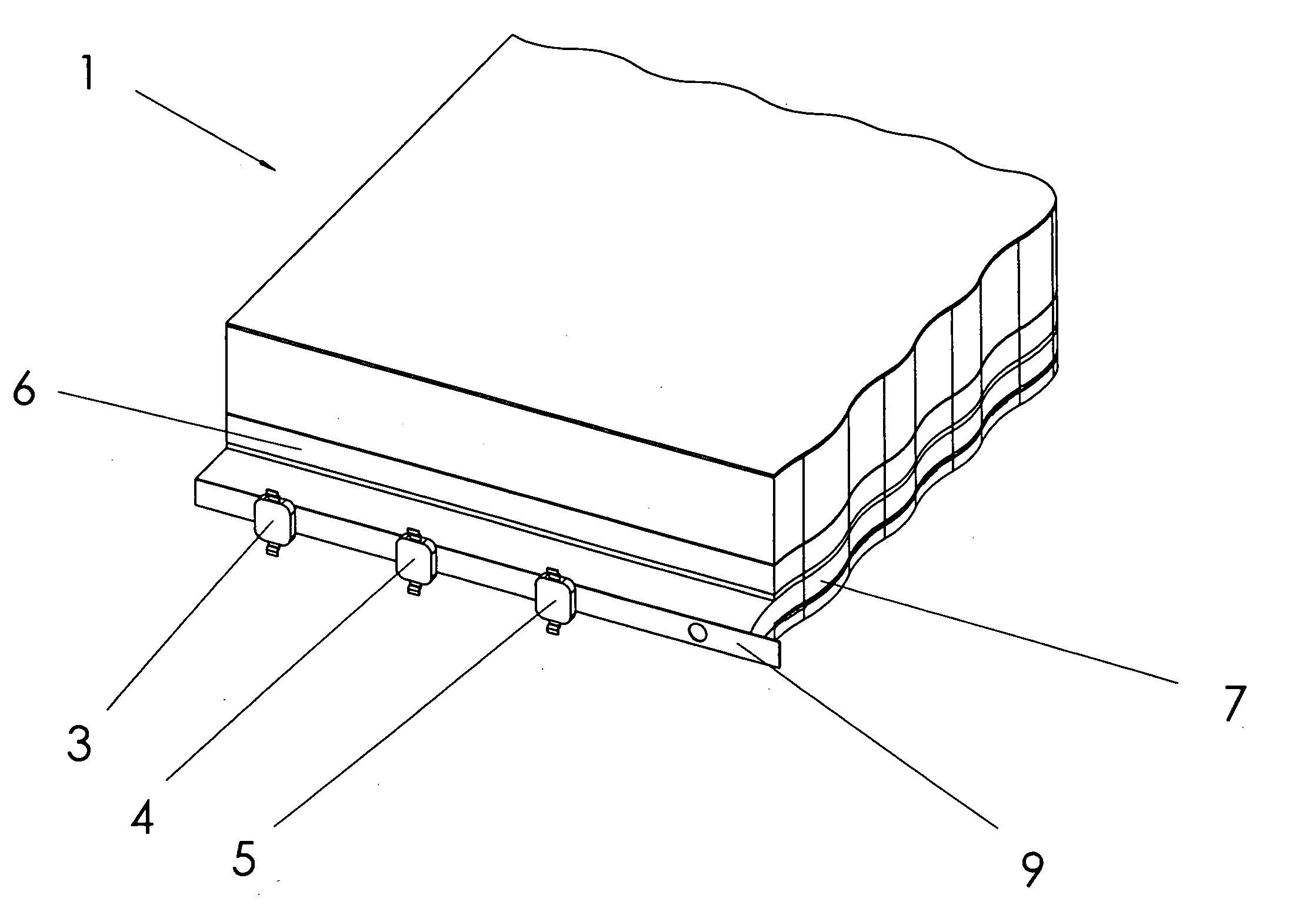
[0078]From these three calculations it can be seen that light will continue to reflect down the light guide 7 when the approach angle of the light rays 41 is less than 62.5 degrees from normal to the surface of the light guide 7. Case 1 and case 3 are conditions where light would TIR. In case 2, the light does not TIR. The light passes through the surface of the light guide 7 and continues along its original path through the contact dome 32.

[0079]It should be noted that the light guide 7 and the contact dome 32 may not have the same index of refraction. If the indexes of refraction are not equal, some refraction will take place at the interface of the light ...


PUM


Abstract

A flat panel display uses pixels that are turned on or off by the enabling or disabling total internal reflection TIR, of a light guide. A reflective surface directs the switched light towards the viewer. An optional mask can be employed to provide extremely high contrast ratios in low and in high ambient lighting conditions. The elements that enable TIR can be enabled quickly because of their small size and weight, resulting in a very fast switching speed. The fast switching speed allows colors to be generated and displayed in a sequential manner.

Description

[0001]Applicant incorporates by reference herein his co-pending application “Optic System for Light Guide with Controlled Output”, filed concurrently with this application.FIELD OF THE INVENTION[0002]This invention relates generally to light display devices, and more particularly is a flat panel display in which the light is switched by enabling and disabling total internal reflection (TIR), and in which the switched light is directed by optics.BACKGROUND OF THE INVENTION[0003]Many products require flat panel displays to display video, computer or other data. Liquid crystal displays, LCDs, have become the dominant technology utilized in flat panel displays. Another, less common technology used for flat panel displays is plasma technology. Other known display technologies used in thicker flat panel displays are of the rear projection type. For very large displays, discrete arrays of LEDs are the dominant technology. These display technologies are used in many types of products includ...

Claims


Application Information

Patent Timeline
Patent Type & Authority Applications(United States)
IPC IPC(8): G09F13/08
CPCG02B6/005G09F9/30G02B6/3522
Inventor RICHARDSON, BRIAN EDWARD
Owner RAMBUS DELAWARE
Why Eureka
Try Eureka