Method and system for measuring angles based on 360 degree images

a technology of 360 degree images and angles, applied in the field of methods and systems for measuring angles, can solve the problems of high cost of electronic angle encoders and may not provide sufficient accuracy for particular applications, and achieve the effect of low cost and high accuracy

Active Publication Date: 2010-07-08
TRIMBLE NAVIGATION LTD
View PDF17 Cites 57 Cited by
  • Summary
  • Abstract
  • Description
  • Claims
  • Application Information

AI Technical Summary

Benefits of technology

[0010]Numerous benefits are achieved using the present invention over conventional techniques. For example, an embodiment according to the present invention provides an inexpensive angle measurement device with high accuracy. Additionally, embodiments of the present invention utilize relatively low cost light sensor arrays (e.g., charge coupled device (CCD) or CMOS arrays) that are commonly used in electronic camera systems and are widely available. Because embodiments are relatively small, they can be incorporated in small systems. Depending upon the embodiment, one or more of these benefits may exist. These and other benefits have been described throughout the present specification and more particularly below.

Problems solved by technology

These electronic angle encoders are expensive and may not provide sufficient accuracy for particular applications.

Method used


Image

  • Method and system for measuring angles based on 360 degree images
  • Method and system for measuring angles based on 360 degree images
  • Method and system for measuring angles based on 360 degree images

Examples


Embodiment Construction

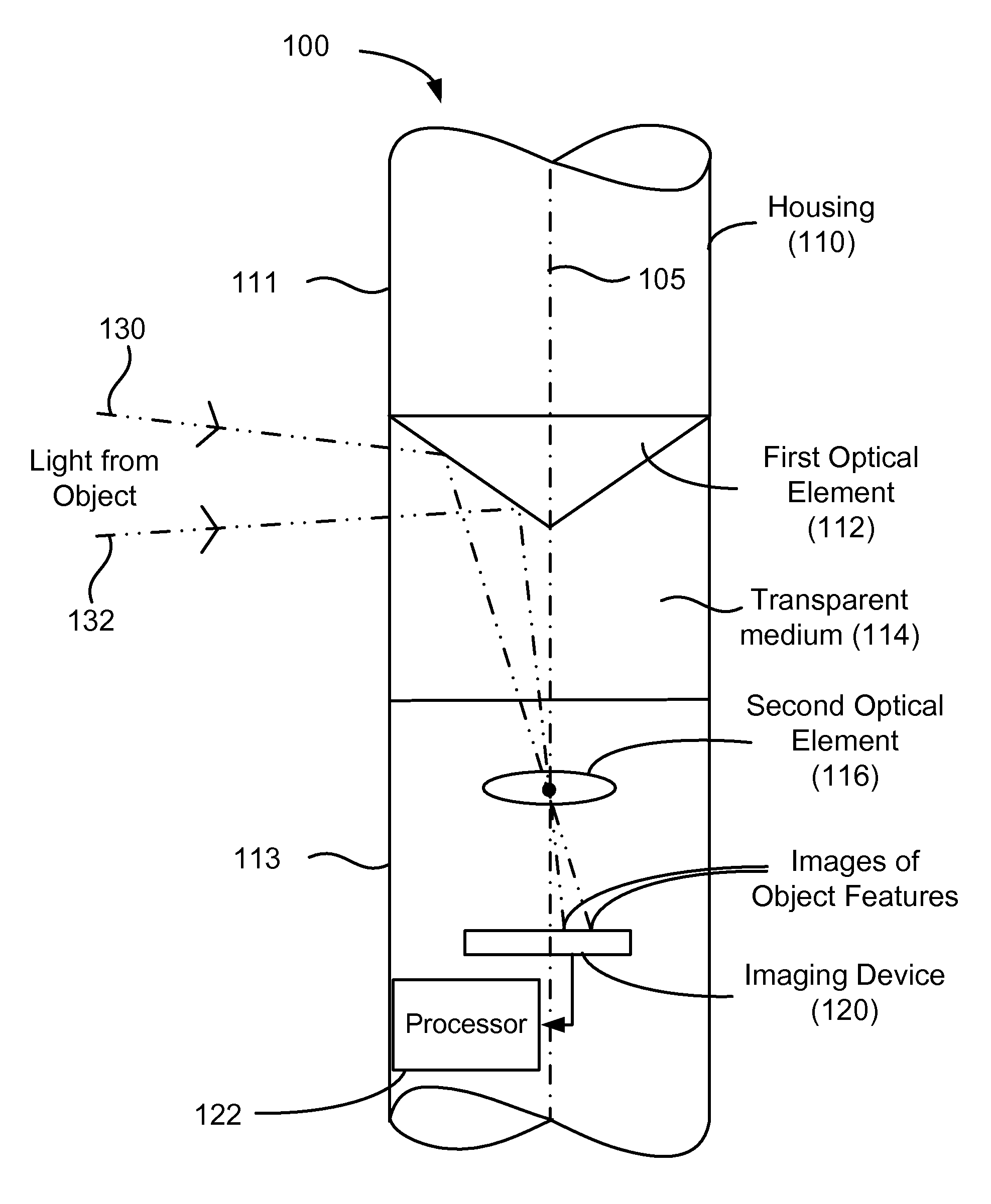
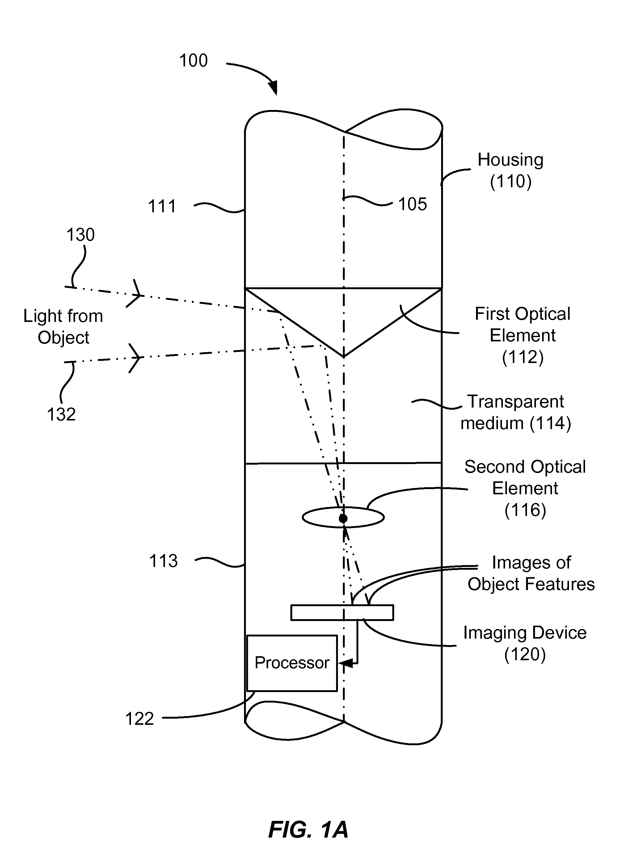
[0031]FIG. 1A is a simplified schematic diagram of an angle measurement system according to an embodiment of the present invention. As illustrated in FIG. 1A, the angle measurement system 100 includes a housing 110 in which one or more of the components of the measurement system are mounted. In a particular embodiment, the housing is a pole, for example, a surveying pole made from a solid material of sufficient strength and rigidity to support the various system components described herein. As an example, the housing may be made from steel, plastic, composite materials, carbon, or the like. A portion of the housing includes a transparent medium or window 114 through which light passes as described more fully throughout the present specification. The transparent medium, which may be made from glass, plastic, or the like, is mounted to the upper portion 111 of the housing and the lower portion 113 of the housing, thereby providing a continuous solid system support extending from the t...


PUM


Abstract

A system for measuring angles includes a housing and an imaging device disposed in the housing. The system also includes a first optical element disposed in the housing and configured to receive light propagating from a first target along a first optical path and direct the light toward the imaging device and receive light propagating from a second target along a second optical path and direct the light toward the imaging device. The system further includes a processor in electrical communication with the imaging device and configured to receive data from the imaging device, compute a 360° angular map based on the received data, and determine an angular separation between the first target and the second target.

Description

BACKGROUND OF THE INVENTION[0001]The present invention relates generally to methods and systems for measuring angles. Merely by way of example, embodiments of the present invention provide a system for acquiring and processing 360° images to provide high resolution angular measurements for surveying applications. However, the scope of embodiments of the present invention is broader than this particular application and can be applied to other applications utilizing angular measurements.[0002]In some surveying operations, a horizontal angle, a vertical angle, and a distance to a target point are measured from a reference point. The measured data may be used to calculate the location of the target point using triangulation techniques. In many small-scale survey operations, one person is responsible for surveying the work site using one or more surveying tools.[0003]A theodolite is a surveying instrument that is commonly used in determining the position of an object, particularly on ina...

Claims


Application Information

Patent Timeline
Patent Type & Authority Applications(United States)
IPC IPC(8): G01B11/26H04N7/18
CPCG01B11/26G06T7/0042G02B13/06G06T7/73
Inventor VOGEL, MICHAELSOUBRA, OMARMUNCY, DARIN
Owner TRIMBLE NAVIGATION LTD
Why Eureka
Try Eureka