Communication apparatus

Inactive Publication Date: 2010-07-08
CANON KK
View PDF5 Cites 6 Cited by
  • Summary
  • Abstract
  • Description
  • Claims
  • Application Information

AI Technical Summary

Benefits of technology

[0011]It is an aspect of the invention to solve such problems and appropriately respond to a request for stopping the power supply, thereby reducing the electricity consumption.

Problems solved by technology

Thus, the standby power, which is consumed when the power is off, becomes large, as a result, the total electricity consumption becomes large.
Thus, a problem may be raised depending on the condition of the connected apparatus.

Method used


Image

  • Communication apparatus
  • Communication apparatus
  • Communication apparatus

Examples


Embodiment Construction

[0032]Exemplary embodiments of the present invention will be described in detail by using the drawings.

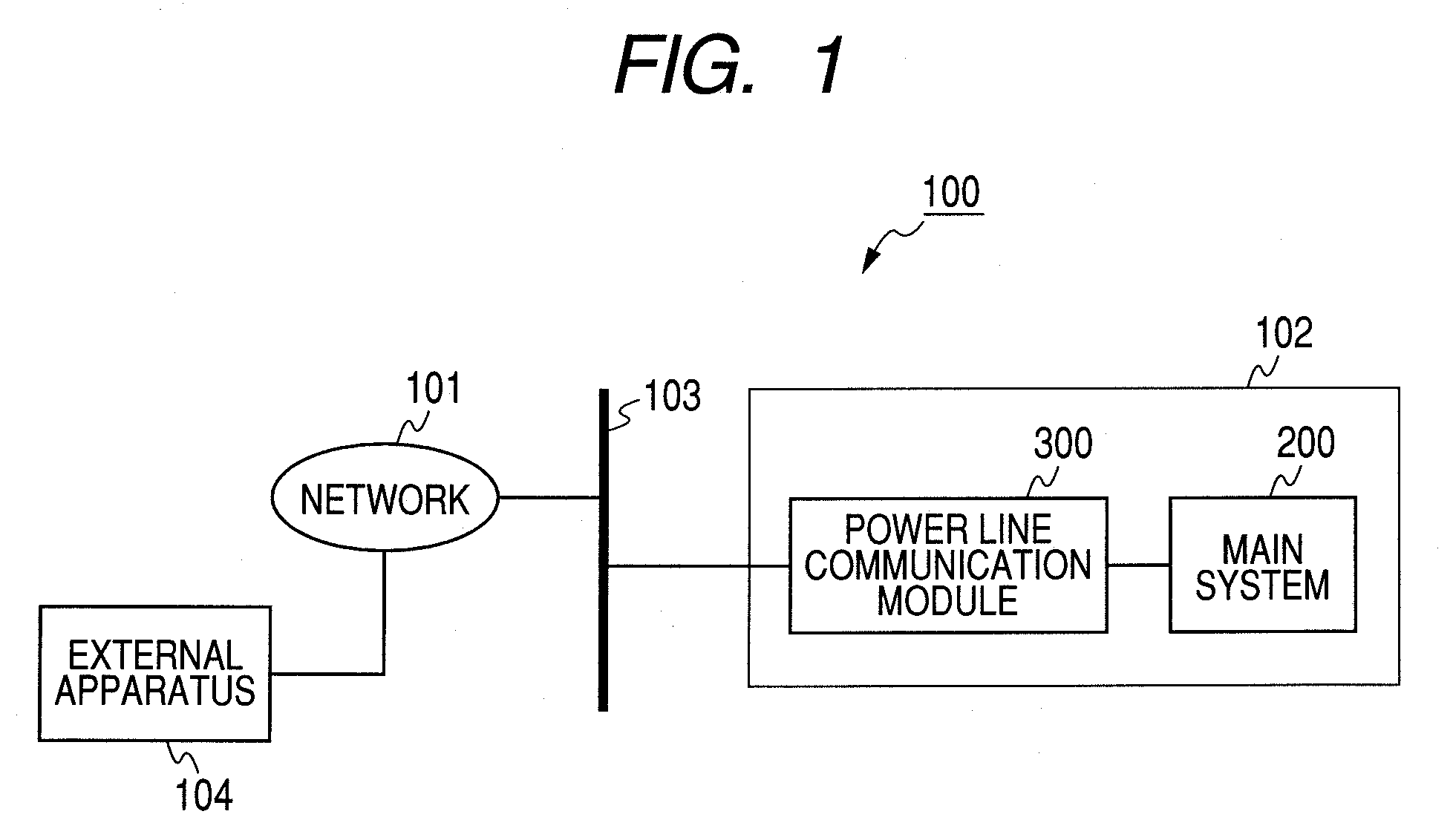
[0033]FIG. 1 illustrates a configuration of a home communication system 100 using the PLC according to a first embodiment of the present invention.

[0034]In the communication system 100 of FIG. 1, a communication apparatus 102 is connected to a home power line 103. An external network 101 is connected to the power line 103, and data can be communicated by the PLC between an external apparatus 104 on the network 101 and the communication apparatus 102. Meanwhile, in the present embodiment, it is assumed that the external apparatus 104 is an apparatus which can control to supply the power to a recorder 102 of the present embodiment.

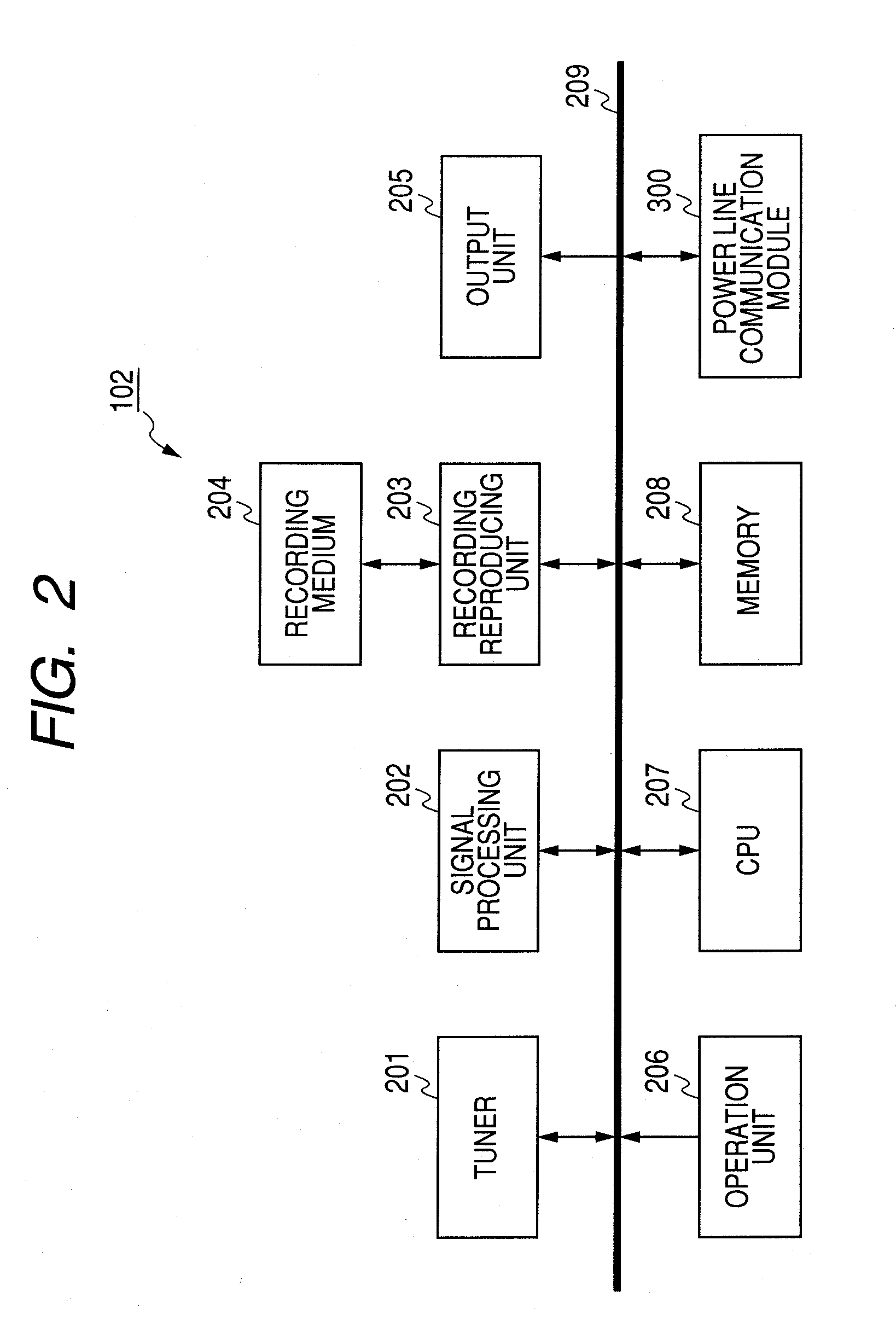
[0035]The communication apparatus 102 is configured with a power line communication module 300 adapted to communicate data with the PLC through the power line 103 and a main system 200 adapted to realize other functions. In the present embodiment, such a ca...


PUM


Abstract

A communication apparatus comprises a connecting unit for connecting with a power line, a circuit for receiving a power supply through the connecting unit, and a communicating unit for communicating with an external apparatus through the connecting unit, a controlling unit for determining whether or not to permit a power supply stop, in accordance with the communicating unit receiving information on a request for the power supply stop, and controlling the communicating unit to transmit response data corresponding to the determination.

Description

TECHNICAL FIELD[0001]The present invention relates to a communication for apparatus, particularly, to an apparatus communicating with an external apparatus connected thereto.BACKGROUND ART[0002]In recent years, a technique has been proposed which connects a home electrical apparatus with a network to control each apparatus by communicating through the network.[0003]A power line communication (PLC) is noticed as such a technique for realizing a home network. The PLC is a method which superimposes a high frequency signal on a existing power line of 100 V (50 / 60 Hz), and bidirectionally communicates by using the power line as a transmission channel (for example, refer to Japanese Patent Application Laid-Open No. 2004-007497).[0004]In the PLC, since an existing power incoming line and an existing power outlet can be utilized as they are, new wiring works are not required. In addition, in the PLC, since the communication can be executed only by inserting a plug to the outlet, the plug an...

Claims


Application Information

Patent Timeline
IPC IPC(8): H04N7/18G05B11/01
CPCG06F1/3209H02J13/0024Y02B60/34H04L12/12H04B2203/5458H02J13/00009Y02D30/50
Inventor ONO, TACHIO
Owner CANON KK
Why Eureka
Try Eureka