Drill ship

a drilling ship and hull technology, applied in the direction of drilling/well accessories, special purpose vessels, sealing/packing, etc., can solve the problems of increasing the cost of moving from one site to another, the real depth limit, and the ship's mobility

Active Publication Date: 2010-07-15
NAT OILWELL VARCO LP
View PDF36 Cites 17 Cited by
  • Summary
  • Abstract
  • Description
  • Claims
  • Application Information

AI Technical Summary

Benefits of technology

[0011]The present invention, in certain aspects, provides a floating system, e.g. a vessel, a drill ship, a rig, (e.g., but not limited to, jack-up rigs and semi-submersible rigs) with a height-adjustable derrick; and, in one particular aspect, a rig, vessel or a drill ship with a derrick having a crown assembly (and, in some aspects, associated structure, e.g. but not limited ...

Problems solved by technology

These, however, are typically used only in relatively shallow depths of water, often not greater than about 300 feet, which is a realistic depth limit for many practical commercial operations.
On the open seas, size and height are generally not a consideration for drill ship movement; but, in certain specific circumstances, size and height limit a drill ship's mobility and can significantly increase the expense of movement from one site to another.
Various prior art drill ships are relatively large.
O...

Method used


Image

  • Drill ship
  • Drill ship
  • Drill ship

Examples


Embodiment Construction

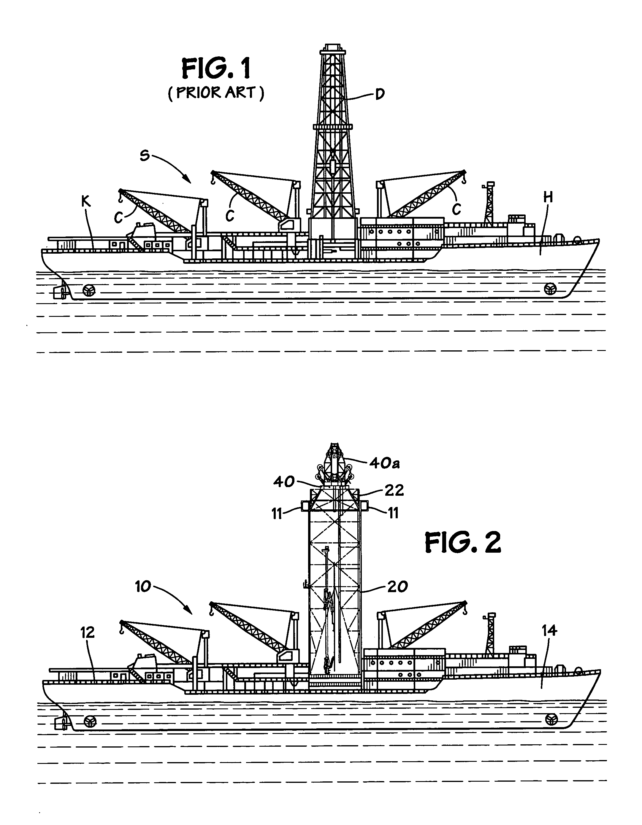
[0055]FIG. 1 shows a typical prior art drill ship S with a deck K on a hull H. One or more cranes C are on the deck K. An upright derrick D is mounted on the deck K.

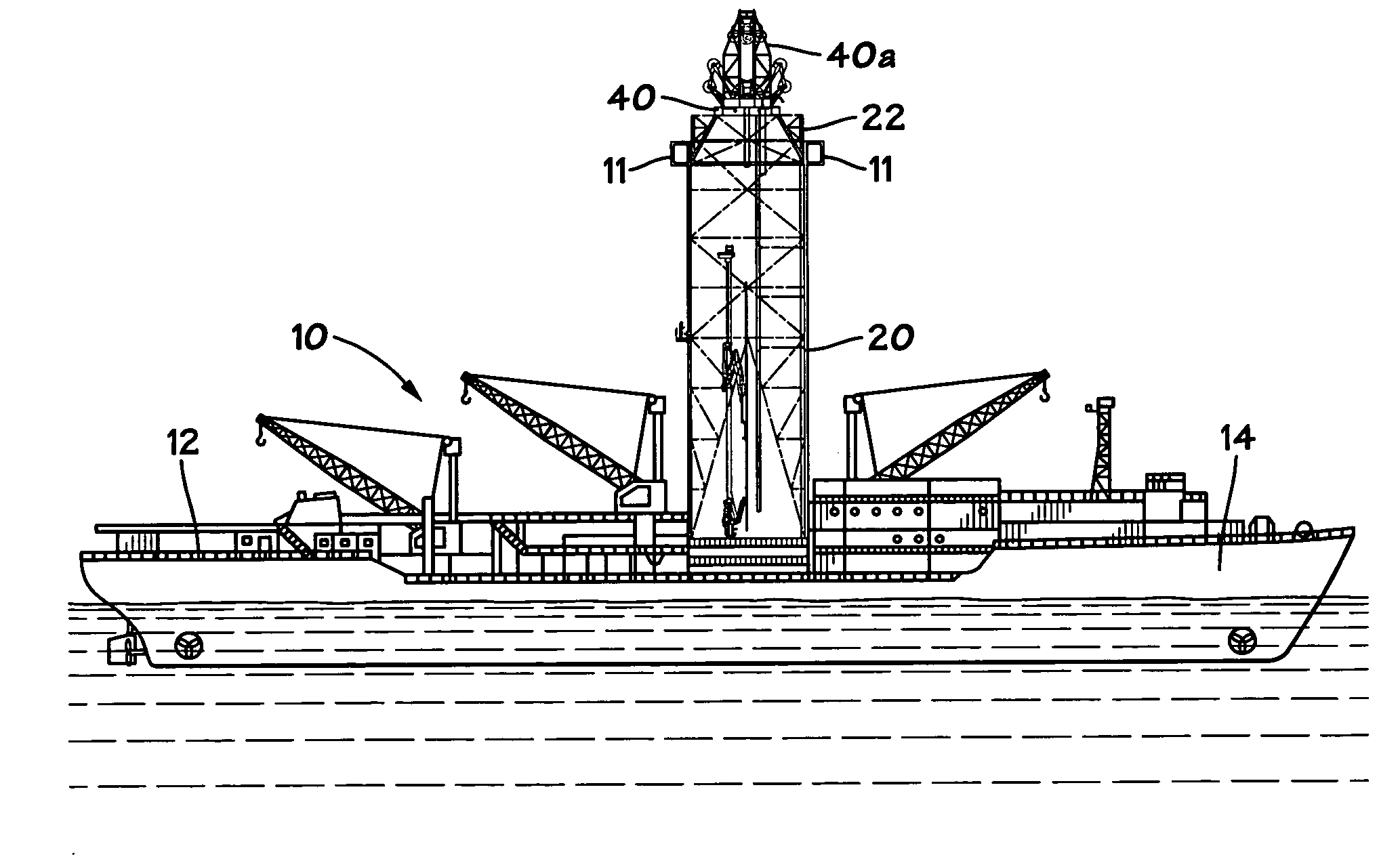
[0056]FIG. 2 shows a floating system 10, e.g., in one aspect, a drill ship, according to the present invention with a deck 12 on a hull 14. A derrick 20 according to the present invention is mounted on the deck 12. The derrick 20 has a crown assembly 40 and an associated (optional) motion compensator 40a releasably and movably connected to a top part 22 of the derrick 20. Movement apparatus 11 (shown schematically) selectively moves the crown assembly 40 and the motion compensator 40a down to reduce the overall weight of the derrick 20. The movement apparatus 11 may be any apparatus disclosed herein.

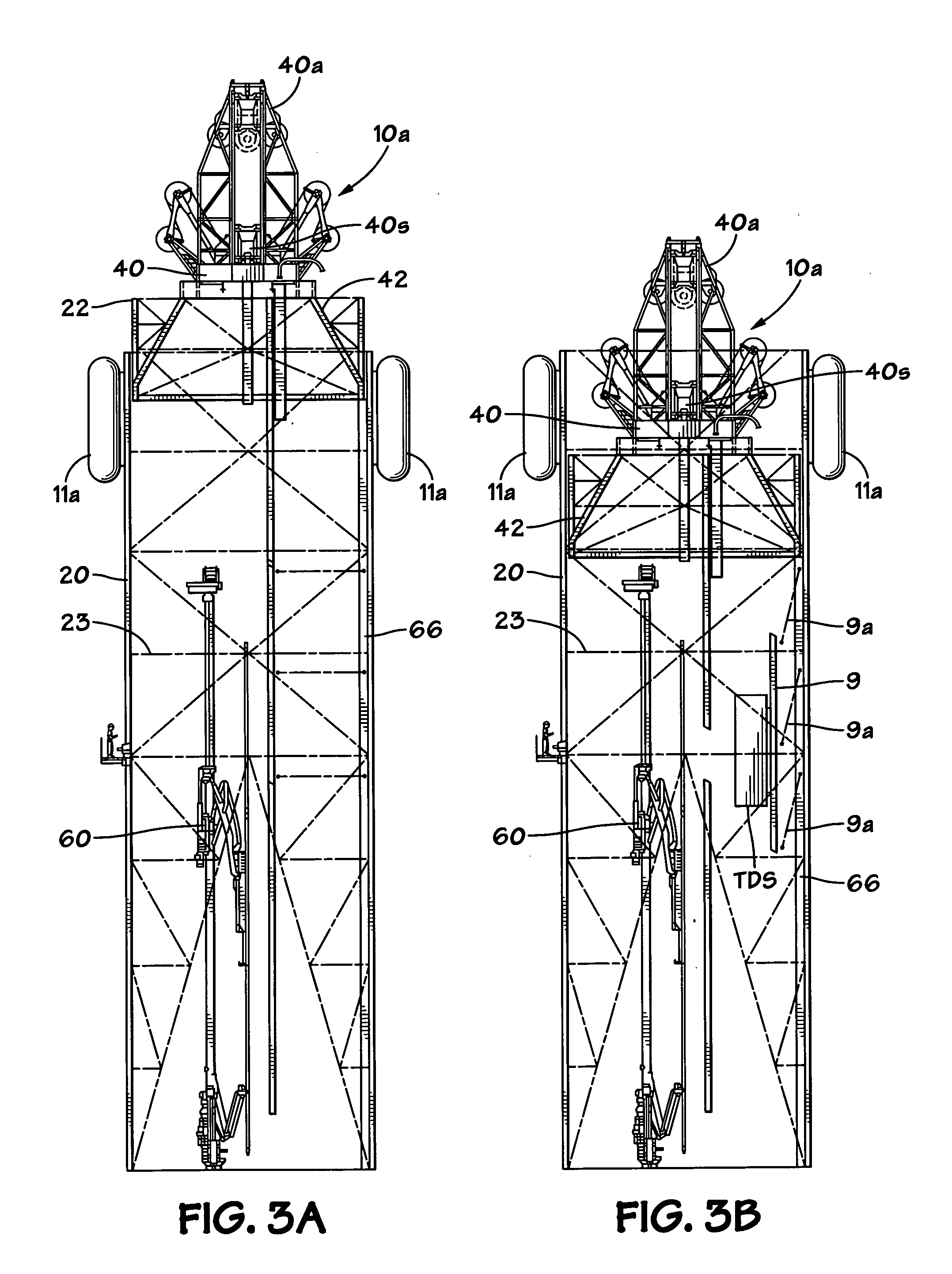
[0057]As shown in FIG. 3A, in an embodiment 10a according to the present invention the derrick 20 has a plurality of crossmembers and braces 23. A pipe handling system 60 connected to the derrick moves pipe, e.g. drill pipe. ...


PUM


Abstract

Floating systems for well operations are disclosed with a height-adjustable crown assembly movably connected to a derrick; in one aspect, movable within the derrick by movement apparatus; and, in one aspect, movable with a motion compensator. This abstract is provided to comply with the rules requiring an abstract which will allow a searcher or other reader to quickly ascertain the subject matter of the technical disclosure and is submitted with the understanding that it will not be used to interpret or limit the scope or meaning of the claims, 37 C.F.R. 1.72(b).

Description

BACKGROUND OF THE INVENTION[0001]1. Field of the Invention[0002]This invention is directed to floating systems, rigs and vessels used in wellbore operations; to floating systems, rigs, drill ships and vessels with a height-adjustable derrick; to methods for selectively adjusting a floating system's center of gravity; and to methods for adjusting derrick height by changing the position of part of a derrick, e.g. a crown block assembly and associated structure.[0003]2. Description of Related Art[0004]Well drilling has been conducted in areas where a substantial body of water overlies an oil field. In many cases a variety of fixed drill platforms mounted on legs resting on or driven into a sea floor or lake floor are used. These, however, are typically used only in relatively shallow depths of water, often not greater than about 300 feet, which is a realistic depth limit for many practical commercial operations.[0005]Often deep water drilling is accomplished using specifically designed...

Claims


Application Information

Patent Timeline
IPC IPC(8): B66C23/52
CPCB63B35/4413E21B19/09E21B15/02
Inventor LUCAS, ALAN RANDALLMCCOO, MARCUS SHERWIN
Owner NAT OILWELL VARCO LP
Why Eureka
Try Eureka