Dipole antenna

Inactive Publication Date: 2010-07-15
ARCADYAN
View PDF4 Cites 8 Cited by
  • Summary
  • Abstract
  • Description
  • Claims
  • Application Information

AI Technical Summary

Benefits of technology

[0007]The invention is directed to a D-type dipole antenna featured by broadband and omni-direction. By the positions of the feeding terminal

Problems solved by technology

Due to the design of the conventional dipole antenna, the oscillation frequency is hard to change and the bandwidth is hard to

Method used


Image

  • Dipole antenna
  • Dipole antenna
  • Dipole antenna

Examples


first embodiment

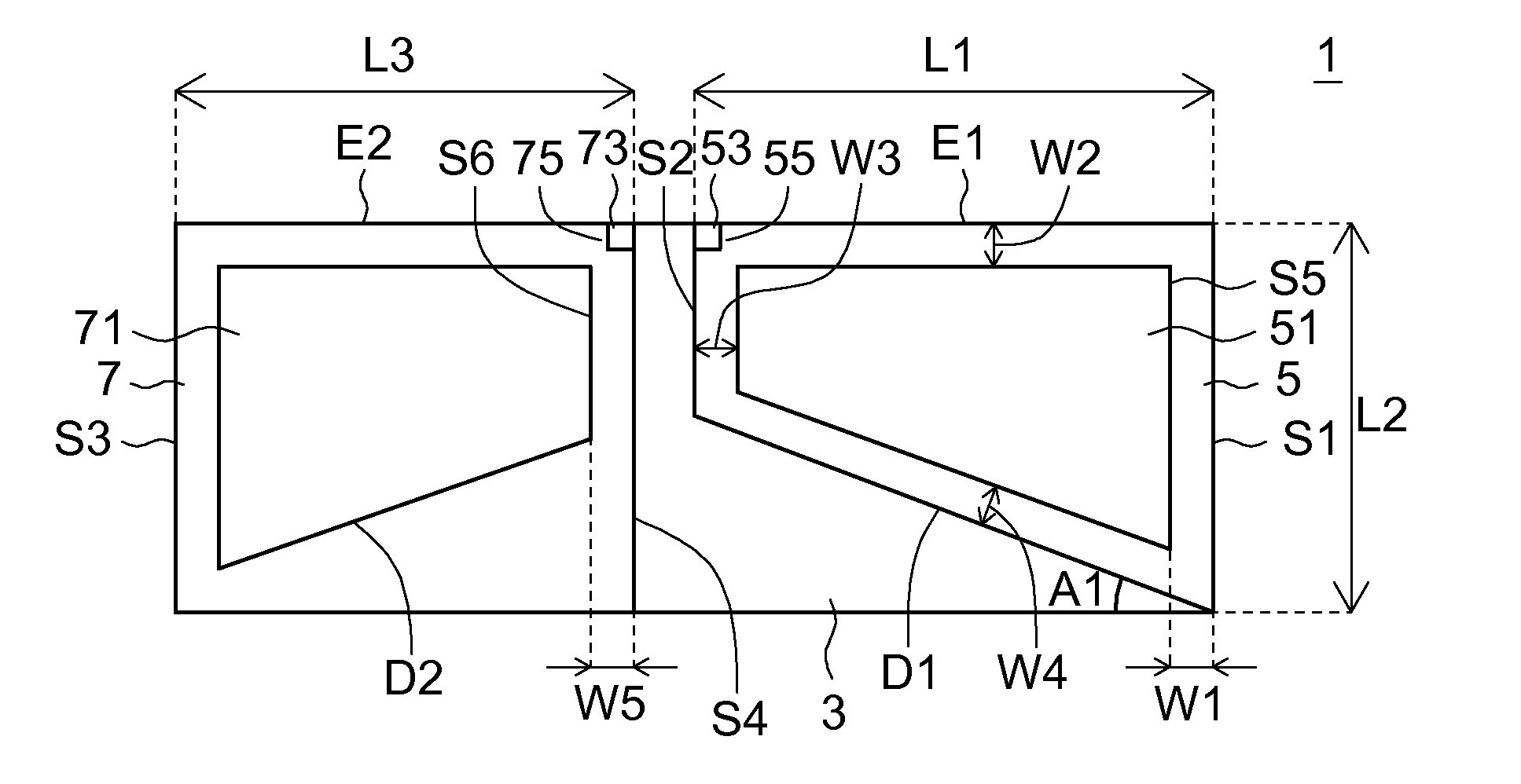
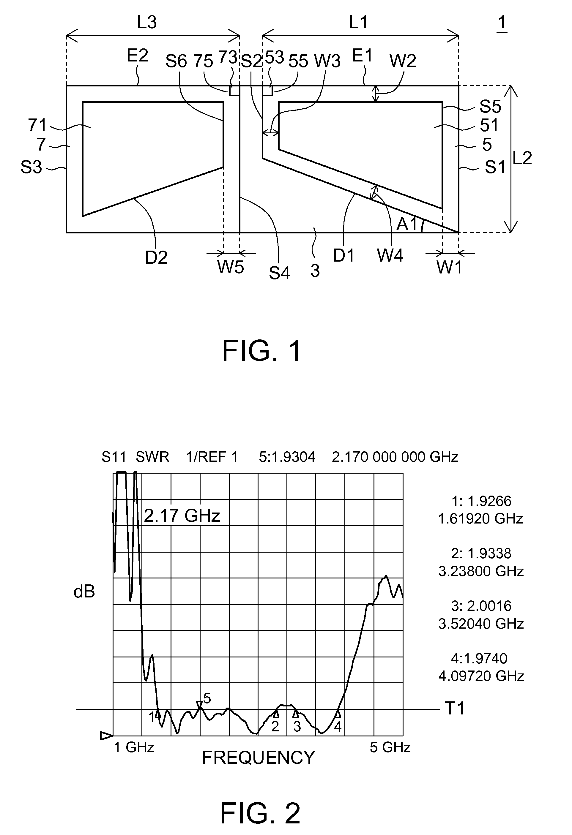
[0025]Referring to FIG. 1, an antenna structure diagram of a first embodiment of the invention is shown. The antenna 1, which can be used in wireless communication devices, supports Institute of Electrical and Electronic Engineers (IEEE) 802.11b / g standard, Worldwide Interoperability for Microwave Access (WIMAX), Digital Enhanced Cordless Telecommunications (DECT), Universal Mobile Telecommunications System (UMTS) wherein respective bandwidth for 802.11b / g, WIMAX, DECT and UMTS are 2.4 GHz˜2.5 GHz, 2.3 GHz˜2.7 GHz, 1.8 GHz˜1.9 GHz, and 1.92 GHz˜2.17 GHz. That is, the antenna 1 of the first embodiment of the invention can be operated within 1.8 GHz˜2.7 GHz.

[0026]The antenna 1 includes a substrate 3, a radiation part 5 and a ground part 7. The substrate 3 is made from flexible substrate, printed circuit board, or high dielectric coefficient circuit board. The radiation part 5 is disposed on the surface of the substrate 3. The outside frame of the radiation part 5 includes a first edge...


PUM


Abstract

The antenna includes a substrate, a radiation part and a ground part. The radiation part is disposed on the substrate. The outside frame of the radiation part is similar to D-type. The radiation part has at least a hole inside. The ground part is also disposed on the substrate. The ground part has at least a hole inside. Positions of a feeding terminal and a ground terminal of the antenna are not limited to center regions of the sides of the radiation part and the ground part.

Description

[0001]This application claims the benefit of Taiwan application Serial No. 98100862, filed Jan. 10, 2009, the subject matter of which is incorporated herein by reference.BACKGROUND OF THE INVENTION[0002]1. Field of the Invention[0003]The invention relates in general to an antenna, and more particularly to a D-type dipole antenna.[0004]2. Description of the Related Art[0005]Along with the rapid advance in science and technology, various slim and compact antennas are provided and used in various slim and compact hand-held electronic devices (such as mobile phone or notebook computer) or wireless communication devices (such as AP (Access Point)). For example, the slim and compact dipole antenna has excellent transmission performance and can be easily disposed on the inner-wall of a hand-held electronic device, has been used in wireless transmission of a large variety of hand-held electronic devices or in wireless communication device.[0006]Due to the design of the conventional dipole a...

Claims


Application Information

Patent Timeline
IPC IPC(8): H01Q9/28H01Q1/48
CPCH01Q1/243H01Q9/285H01Q9/26
Inventor LEE, CHANG-JUNGDU, JIAN-JHIH
Owner ARCADYAN
Why Eureka
Try Eureka