Optical pickup device and collimate lens

Active Publication Date: 2010-07-15
PANASONIC CORP
View PDF6 Cites 6 Cited by
  • Summary
  • Abstract
  • Description
  • Claims
  • Application Information

AI Technical Summary

Benefits of technology

[0042]According to the first aspect of the present invention, there is provided a structure which performs coma-aberration correction, separately, by the first coma-aberration correction actuator for inclining the objective lens in the first tilt direction and the second coma-aberration correction actuator for inclining the coma-aberration correction lens in the second tilt direction. This can simplify the respective suspension structures for supporting the objective lens and the coma-aberration correction lens, which can reduce the size of the coma-aberration correction actuator. This can realize reduction of the size and the thickness of the optical pickup device.
[0043]Further, according to the second aspect and the third aspect of the present invention, the coma-aberration correction lens is constituted by a collimating lens suitable for designs having coma-aberration correcting functions. This can reduce the number of components, as a matter of cause, and also can reduce the volume occupied by the optical system, thereby realizing further reduction of the size and the thickness of the optical pickup device.
[0044]Further, the first tilt direction is set to the direction of the correction of coma aberrations in the radial direction of the optical recording medium, which enables correcting the coma aberration in the radial direction which is required to be corrected over a large range, by the first coma-aberration correction actuator which can be easily inclined in the radial direction. This enables effective utilization of the occupied volume. Further, the second tilt direction is set to the direction of the correction of coma aberration in the tangential tilt direction of the optical recording medium. This enables making the axis for the inclination of the coma-aberration correction lens to be along a direction parallel with the optical recording medium, in the case where the optical axis of the coma-aberration correction lens is made parallel with the tangential direction of the optical recording medium. Accordingly, by making the optical axis thereof parallel with the tangential direction of the optical recording medium, it is possible to reduce the size of the optical pickup device in the direction parallel with the radial direction of the optical recording medium. This can reduce the size of the optical disc device which incorporates the optical pickup device, in a depth direction along the direction parallel with the radial direction. Furthermore, even when a suspension for rotatably supporting the coma-aberration correction lens is structured, it is possible to prevent the optical pickup device from having an increased size in a thickness direction, namely in the thickness direction of the loaded optical disc, thereby realizing reduction of the sizes and the thicknesses of the optical pickup device and the optical disc device.
[0045]By applying the optical pickup device according to the present invention to a thin-type optical pickup device having a height of 21 mm or less from the lower surface of the optical base to the apex of the objective lens, it is possible to realize reduction of the size and the thickness more effectively.
[0046]Further, by applying the optical pickup device according to the present invention to an optical pickup device adapted such that the optical axis of the coma-aberration correction lens is parallel to the tangential direction of the optical recording medium, it is possible to preferably place the axis for the inclination of the coma-aberration correction lens in a direction parallel to the optical recording medium. Since the optical axis is made parallel to the tangential direction of the optical recording medium, it is possible to reduce the size of the optical pickup device in the direction parallel to the radial direction of the optical recording medium. This can reduce the size of the optical disc device including the optical pickup device in the depth direction (the direction parallel to the radial direction). Furthermore, even when a suspension for rotatably supporting the coma-aberration correction lens is structured, it is possible to prevent the optical pickup device from having an increased size in the thickness direction, namely in the thickness direction of the loaded optical disc, which can realize reduction of the sizes and the thicknesses of the optical pickup device and the optical disc device.
[0047]Further, by employing the objective-lens actuator including the rod-type elastic support member for supporting the movable member movably in the focusing direction, the tracking direction and the first tilt direction with respect to the base, it is possible to realize the first coma-aberration correction actuator without changing the suspension for the objective lens.

Problems solved by technology

However, the coma-aberration correcting method using the liquid crystal device can correct only angular deviations at low frequencies and, therefore, has the problem of difficulty in reducing coma aberrations induced over a wide range from a low frequency to a high frequency.
Further, the coma-aberration correcting method has the problem that a liquid crystal device is more expensive than a lens, which prevents cost reduction.

Method used


Image

  • Optical pickup device and collimate lens
  • Optical pickup device and collimate lens
  • Optical pickup device and collimate lens

Examples


first embodiment

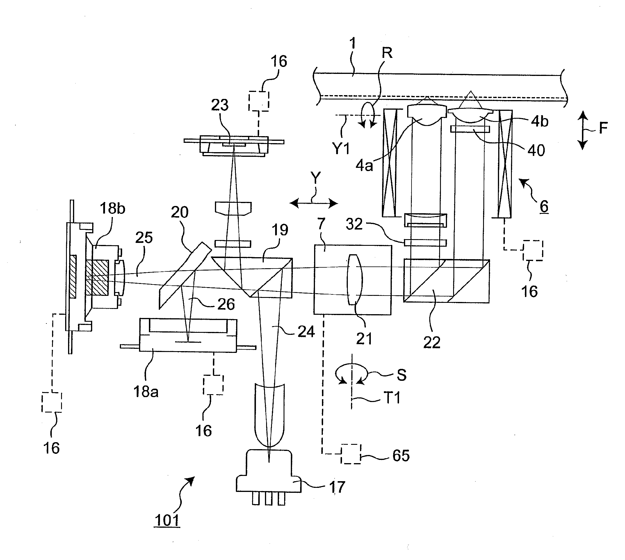
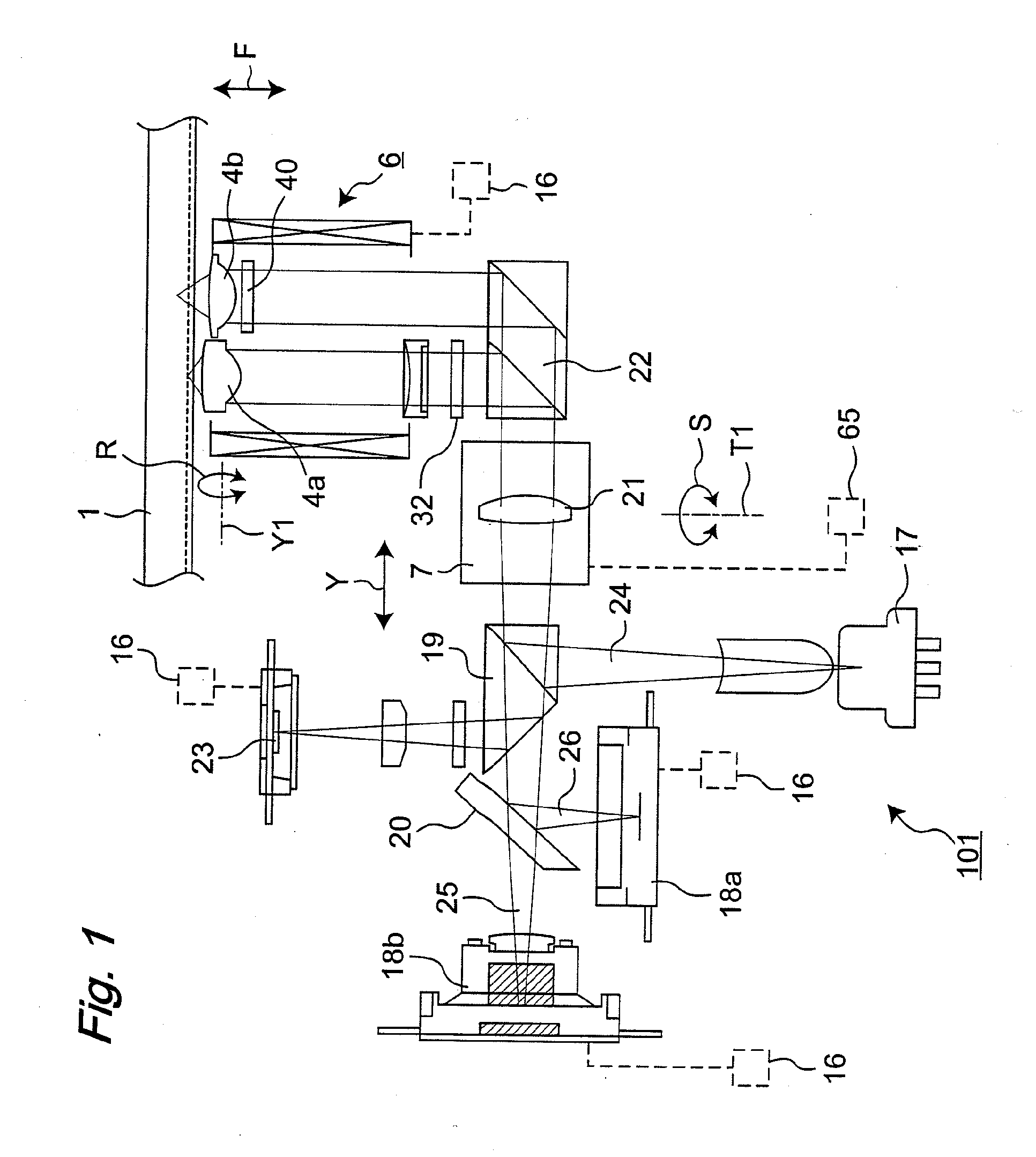
[0099]With reference to FIG. 1, there will be described a structure of an optical pickup device 101 according to a first embodiment of the present invention.

[0100]The optical pickup device 101 according to the present embodiment is an optical pickup device which records and plays back information, by condensing a luminous flux emitted from a light source toward an optical disc as an optical recording medium, onto the optical recording medium through a light-condensing optical system. This optical pickup device 101 generally includes the light source, a first coma-aberration correction actuator and a second coma-aberration correction actuator. In this case, the first and second coma-aberration correction actuators constitute a portion of the light-condensing optical system. Further, the first coma-aberration correction actuator includes a first tilt drive portion for inclining, in a first tilt direction, an objective lens for converging the emitted light to the optical disc. The seco...

second embodiment

[0195]Hereinafter, an optical pickup device according to a second embodiment of the present invention will be described, with reference to the drawings.

[0196]FIG. 11 is a structural view illustrating the structure of a collimating lens actuator 7-2 in the optical pickup device according to the second embodiment.

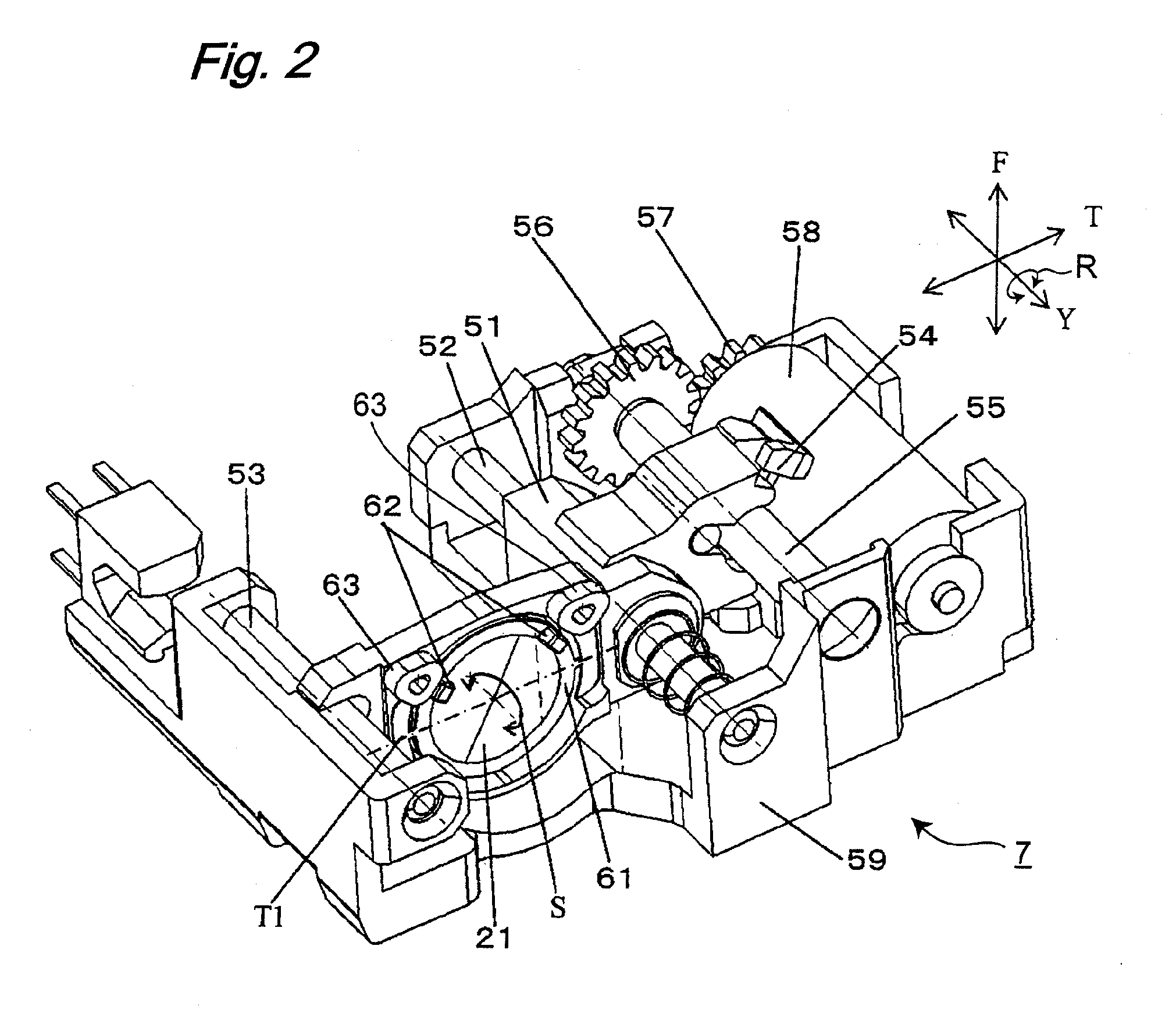
[0197]Referring to FIG. 11, the collimating lens actuator 7-2 is different from the collimating lens actuator 7 illustrated in FIG. 2, in that the movable magnets 62 and the fixed tangential tilt coils 63 in the tangential tilt drive portion in the collimating lens actuator 7 are replaced with fixed magnets 66 and a movable tangential tilt coil 67 in the collimating lens actuator 7-2 according to the second embodiment. No changes are made to the other components of the collimating lens actuator 7-2, and the components having the same functions as those of the collimating lens actuator 7 are designated by the same reference characters.

[0198]Accordingly, hereinafter, the collim...

third embodiment

[0201]Hereinafter, an optical pickup device according to a third embodiment of the present invention will be described, with reference to the drawings.

[0202]FIG. 12 is a structural view illustrating the structure of a collimating lens actuator 7-3 in the optical pickup device according to the third embodiment.

[0203]Referring to FIG. 12, the collimating lens actuator 7-3 is different from the collimating lens actuator 7 illustrated in FIG. 2, in that the movable magnets 62 and the fixed tangential tilt coils 63 in the tangential tilt drive portion in the collimating lens actuator 7 are replaced with a piezoelectric device 68 in the collimating lens actuator 7-3 according to the third embodiment. No changes are made to the other components of the collimating lens actuator 7-2, and the components having the same functions as those of the collimating lens actuator 7 are designated by the same reference characters.

[0204]Accordingly, hereinafter, the collimating lens actuator 7-3 will be ...


PUM


Abstract

It is an object of the present invention to provide an optical pickup device being capable of correcting coma aberration induced in a light-condensing optical system including an objective lens for an optical disc and having a reduced size and a reduced thickness in comparison with the conventional art. The present invention includes a first coma-aberration correction actuator (6) including a first tilt drive portion for inclining an objective lens in a first tilt direction, and a second coma-aberration correction actuator (7) including a second tilt drive portion for inclining, in a second tilt direction, a coma-aberration correction lens placed between a light source and a raising mirror for reflecting emitted light toward the objective lens.

Description

TECHNICAL FIELD[0001]The present invention relates to an optical pickup device which plays back or records information from or on information recording mediums represented by optical discs and, also, a collimating lens included in the optical pickup device.BACKGROUND ART[0002]Digital versatile discs (DVDs) are known as optical discs capable of storing large-capacity data, since they can store digital information with recording densities of about 6 times those of compact discs (CDs). In recent years, along with increases of amounts of information to be recorded in optical discs, there has been a need for optical discs with larger capacities. In order to increase the capacity of an optical disc, it is necessary to reduce the size of a light spot formed by light directed to the optical disc during recording information onto the optical disc and during playing back information recorded on the optical disc to increase the information recording density. The size of the light spot can be r...

Claims


Application Information

Patent Timeline
IPC IPC(8): G11B7/00G11B7/135
CPCG11B7/0956G11B2007/0006G11B7/13927
Inventor WAKABAYASHI, KANJIYAMASAKI, FUMITOMOKOMMA, YOSHIAKITOMITA, HIRONORI
Owner PANASONIC CORP
Why Eureka
Try Eureka