Optical pickup device

Inactive Publication Date: 2007-07-24
SHARP KK
View PDF20 Cites 0 Cited by
  • Summary
  • Abstract
  • Description
  • Claims
  • Application Information

AI Technical Summary

Benefits of technology

[0040]In view of the above conventional problems, an object of the present invention is to provide an optical pickup device, using a diffraction element, which can be provided in a reduced size and thickness, which causes no offset in a tracking error signal, and which can discriminate between a land and a groove, even when there is a variation in sensitivity of a light receiving element, rotation efficiency of a diffraction element, or operation circuits.
[0046]This makes it possible to obtain an accurate signal waveform having no phase difference with respect to SPP1−αSPP2 (α is a constant), thereby obtaining an ideal land / groove discriminating signal from a difference between SPP1 and αSPP2.
[0047]The above arrangement makes it possible to remove an land / groove discriminating offset caused by a difference in magnitude of push-pull signals from the subspots in case of an adjustment error of subbeam projection positions with respect to the disk track, thereby accurately distinguishing between the lands and grooves all the time and performing an excellent pull-in operation of the tracking servo.
[0054]Therefore, when (SPP1+αSPP2) is subtracted from the MPP of the main beam having a tracking offset, a tracking offset component can be cancelled completely. This makes it possible to obtain a tracking signal having no offset, and to perform accurate tracking control.
[0055]The above arrangement makes it possible to adjust an AC amplitude of SPP2 so as to generate an accurate tracking error signal all the time even in the presence of a variation in size of SPP1 and SPP2 from the subspots or an adjustment error of subbeam projection positions with respect to the disk track, thereby realizing an excellent tracking servo.

Problems solved by technology

Accordingly, with respect to the differential signal D11-D12, a problem arises that a tracking offset occurs due to the difference in quantity of reflected light, not due to a tracking deviation.
However, the push-pull method has the following problem.
Thus, in both cases, there is a problem that despite no tracking deviation, a differential signal D11′-D12′ from the dichotomized photodetector 115 is offset to cause inaccurate tracking.
However, the TES and L / G discriminating signal have the following problems.
As a result, as shown in FIG. 12(b), there is a problem that the additional residual offset is added to TES, and the signal phase of the TES shifts by ø from the proper signal phase, so that accurate tracking control cannot be performed.
Furthermore, the following will explain a problem caused by a tracking error signal when an adjustment error occurs in positioning subbeams on the optical disk when assembling and adjusting the pickup.
As a result, there is a problem that the residual offset is added to the TES, and the signal phase of the TES is out of phase by øb from the ideal TES phase, so that accurate tracking control cannot performed.
However, since (As-Bs) and (Cs-Ds) are out of phase, as shown in FIG. 13(c), the phase of the L / G discriminating signal is out of phase by øc from the ideal discriminating signal, so that accurate land / groove discrimination cannot be performed.
Accordingly, the tracking servo system cannot perform a pull-in operation.
Incidentally, the residual offset tends to become larger as the adjustment error becomes large in positioning subbeams on the optical disk when assembling and adjusting the pickup.
Therefore, conventional pickups must be assembled so that an adjustment error in positioning subbeams becomes as small as possible.
This means greater difficulties in assembling and lower yield, resulting in rise in manufacturing cost.

Method used


Image

  • Optical pickup device
  • Optical pickup device
  • Optical pickup device

Examples


Embodiment Construction

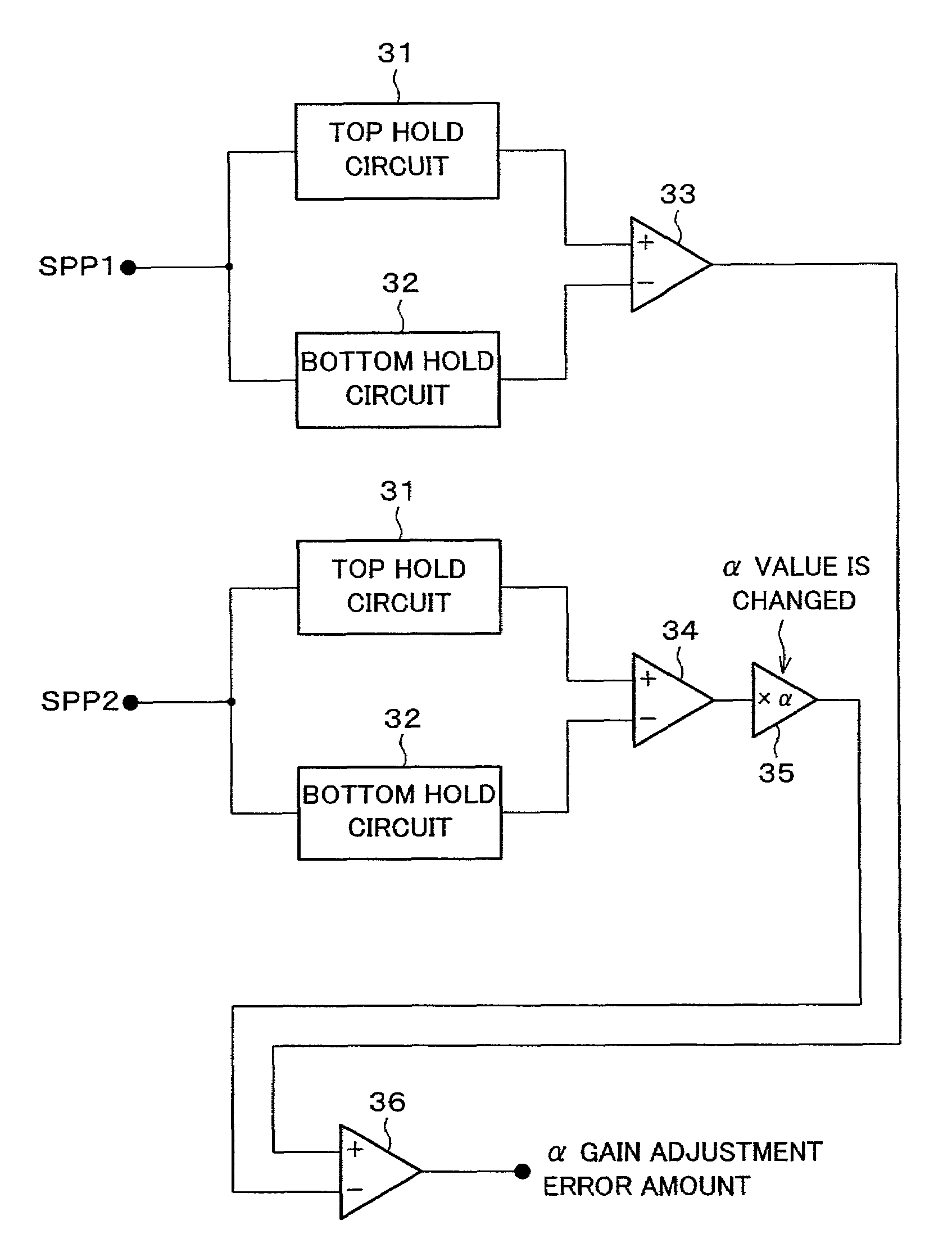
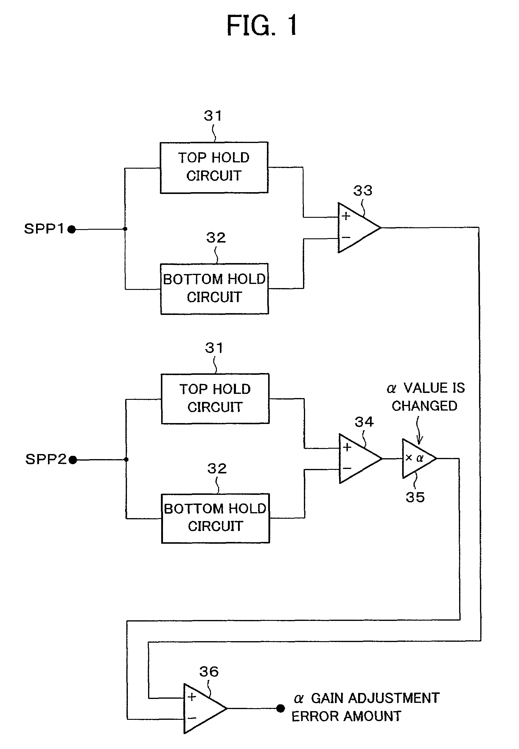
[0071]Referring to FIG. 1 to FIG. 7, the following will explain an embodiment of the present invention.

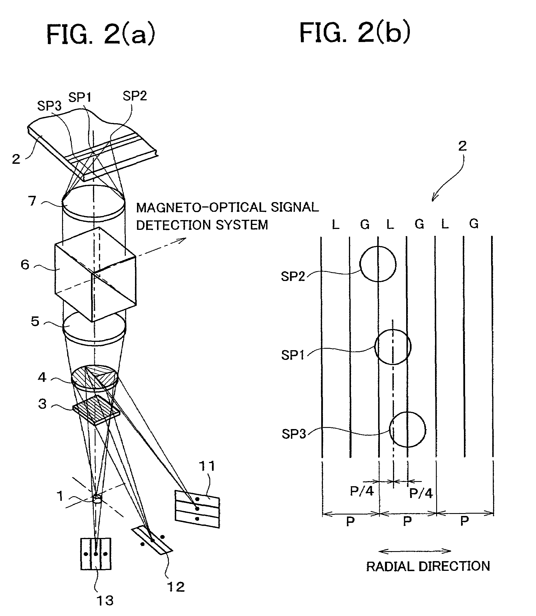
[0072]FIG. 2(a) is a perspective view illustrating an optical system in an optical pickup device of the present embodiment. Between a semiconductor laser 1 as a light source and an optical disk 2 are disposed a first diffraction element 3, a second diffraction element 4, a collimator lens 5, a beam splitter 6, and an objective lens 7 in order from the semiconductor laser side, centered by an optical axis.

[0073]The first diffraction element 3 and the second diffraction element 4, which are dispersing elements utilizing the diffraction effect of light, function to disperse incident light. The optical disk 2 has a track which is defined by a groove part, which is a recessed part, and a land part, which is a raised part, of approximately the same width. The collimator lens 5 functions to convert emitted laser light into parallel laser light. The beam splitter 6 is an optical element wh...


PUM


Abstract

According to the present invention, an optical pickup device forms one main spot, a first subspot, and a second subspot by irradiation of light on an optical disk having a groove part and a land part. The optical pickup device includes operation circuits which indicate a deviation between each of the optical spots and a track, and α detecting means for detecting such an α value that a difference in absolute value between SPP1 and αSPP2 falls in a preset range, where an AC amplitude of a push-pull signal of the first subspot is SPP1, and an AC amplitude of a push-pull signal of the second subspot is SPP2, wherein SPP1−αSPP2 (α is a constant) is a land / groove discriminating signal. With this, in the optical pickup device for recording and reproducing information on / from the optical disk having a land / groove part, it is possible to generate a land / groove discriminating signal and a tracking error signal without an offset, thereby performing excellent tracking control.

Description

FIELD OF THE INVENTION[0001]The present invention relates to an optical pickup device used in optical reproducing apparatuses which reproduce a read-only optical disk such as a compact disk (CD) and a laser disk (LD), or in optical recording and reproducing apparatuses which record and reproduce information with respect to an optical disk such as a write-once type or a rewritable type optical disk.BACKGROUND OF THE INVENTION[0002]An optical pickup must trace accurately tracks of 1.6 μm intervals in an optical disk such as a CD. Accordingly, in order to ensure stable signal detection, control at one-tenth or less a track width is required, and a control operation (tracking servo) is generally performed with a tolerance of 0.1 μm or less.[0003]In an optical pickup device, this control operation is performed by moving an objective lens back and forth in a horizontal direction, and it is necessary to detect a signal (tracking error signal) which indicates a direction (right or left) and...

Claims


Application Information

Patent Timeline
IPC IPC(8): G11B7/09G11B7/085G11B7/00G11B7/007G11B7/13G11B7/131G11B7/135G11B7/1353G11B7/1381
CPCG11B7/0903G11B7/0945G11B7/131G11B7/1353G11B7/1381G11B11/10543G11B11/10576G11B11/10584G11B7/00718
Inventor MIYAKE, TAKAHIRO
Owner SHARP KK
Why Eureka
Try Eureka