Noise Reducing Earphone

a technology of earphones and earphones, applied in the field of noise reduction earphones, can solve the problems of user's general inability to sacrifice, and achieve the effects of reducing the distance between the speaker and the sound tunnel, sacrificing the high frequency performance of the earphones, and reducing the decay of high frequency

Inactive Publication Date: 2010-07-15
MERRY ELECTRONICS CO LTD
View PDF9 Cites 41 Cited by
  • Summary
  • Abstract
  • Description
  • Claims
  • Application Information

AI Technical Summary

Benefits of technology

[0007]In view of the foregoing, an objective of the present invention is to provide a noise reducing earphone that reduces noise and has a relative good output frequency response.
[0010]As mentioned above, the present invention places the microphone besides the speaker, the distance between the speaker and the sound tunnel is greatly reduced and the high frequency decay that exists in the conventional noise reducing earphones is shifted to be in a higher frequency range that is beyond normal human audible range. By this means, the introduction of noise reduction functionality does not lead to sacrifice of high frequency performance of the earphone and instead gives the user a better hearing experience. In addition, an opening is formed on the edge of the cavity, and a damping element is used to control the opening to be open or closed so that the noise insertion loss presents a relatively large dB value in a relatively wide range of frequencies, which means noise reduction is achieved equally well at different frequencies in that wide frequency range. Hence, the overall noise reduction is enhanced.

Problems solved by technology

Hence it is evident that the sound output performance of the conventional in-ear noise reducing earphone is sacrificed by the positioning of the microphone and such sacrifice is generally not desired by the user.

Method used


Image

  • Noise Reducing Earphone
  • Noise Reducing Earphone
  • Noise Reducing Earphone

Examples


first embodiment

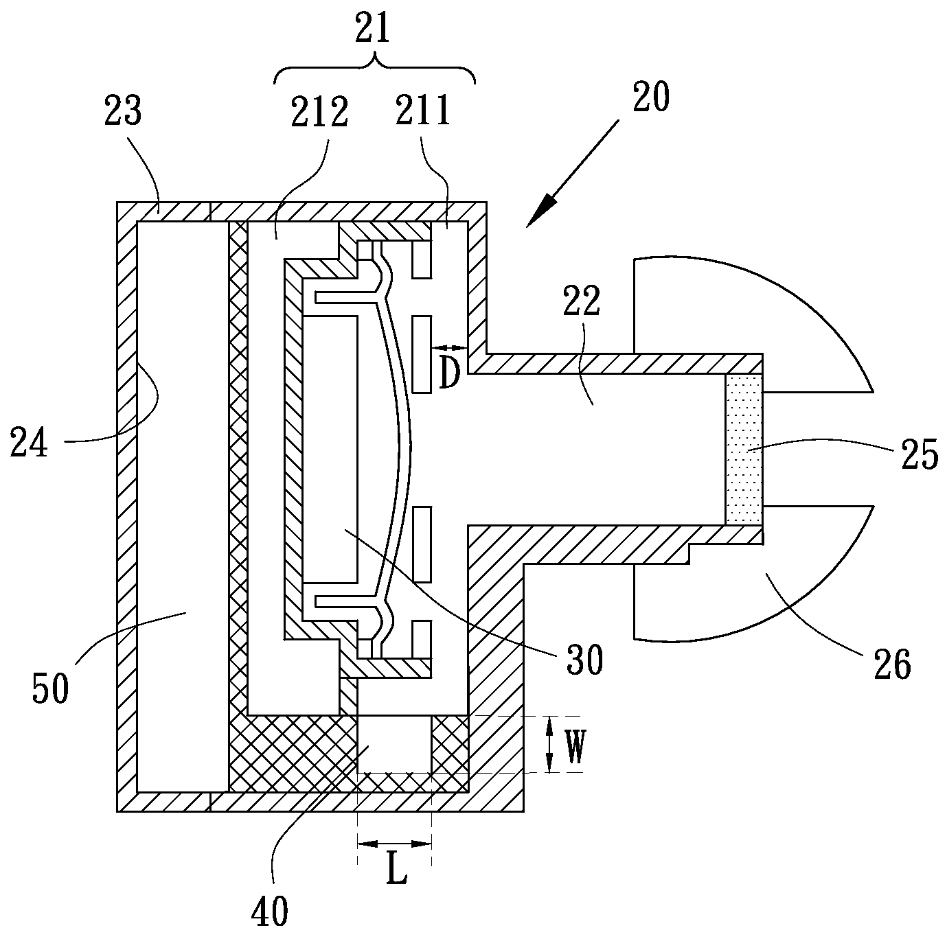
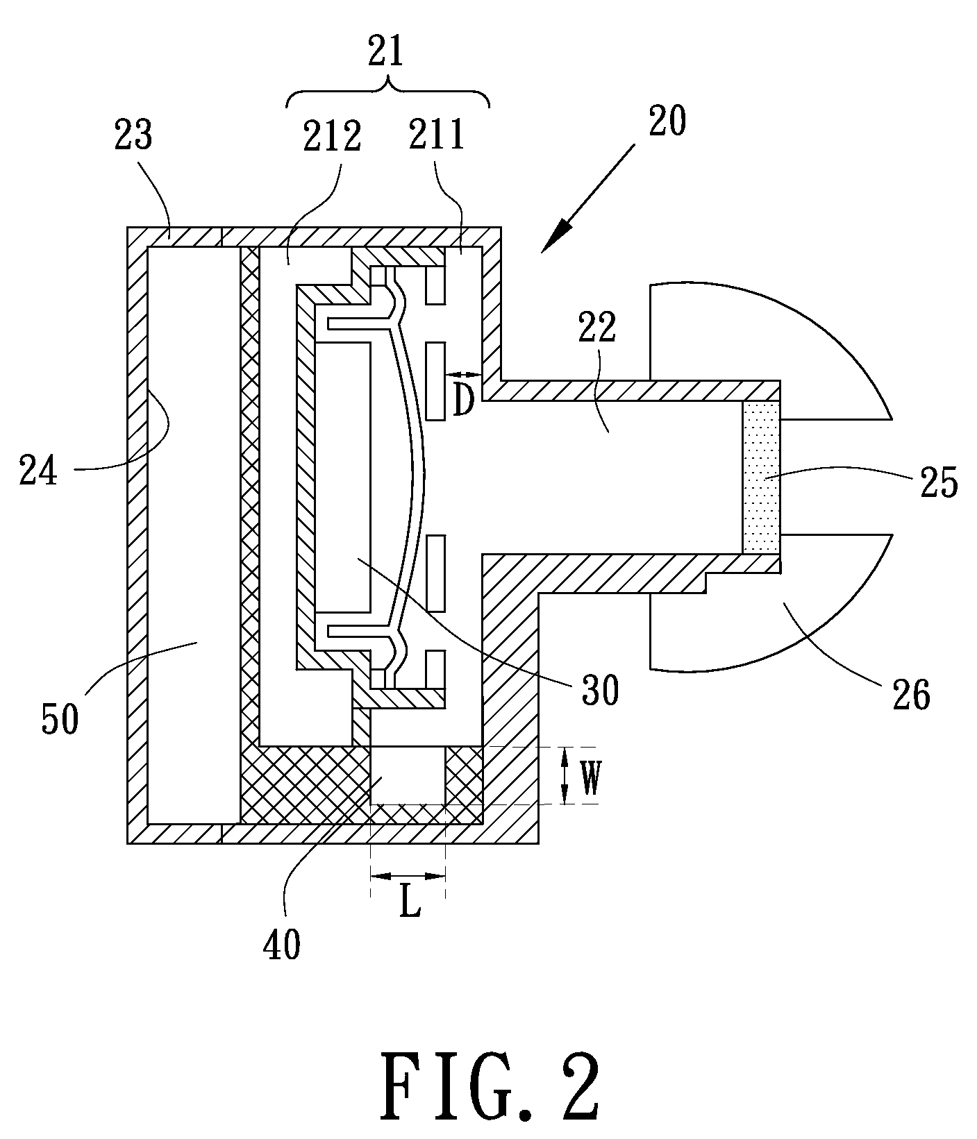
[0021]Referring to FIG. 2, a noise reducing earphone according to the invention is provided. The noise reducing earphone includes a body 20, a speaker 30, a microphone 40 and a signal processor 50. The body 20 includes a cavity 21 and a sound tunnel 22. The cavity 22 is connected to the outside through the sound tunnel 22. The speaker 30 and the microphone 40 are both disposed in the cavity 21. The speaker 30 is positioned in the way that it divides the cavity 21 into a front cavity 211 and a rear cavity 212. The microphone 40 is disposed in the front cavity 211 and besides the speaker 30. The signal processor 50 is electrically connected to the speaker 30 and the microphone 40, and configured for providing an electrical signal to the speaker 30 so that the electrical signal is converted to an audio signal and the audio signal is output from the sound tunnel 22. The microphone 40 is configured for receiving the audio signal and other audio signals for example echoes generated from t...

second embodiment

[0027]FIGS. 5A to 5C illustrate the frequency responses of sensitivity, phase and noise insertion loss of the noise reducing earphone in different opening status. In FIG. 5A, when a user closes the opening 27 with the damping element 60 a sensitivity frequency response curve F2 is measured; when the user moves the damping element 60 and opens the opening 27, another sensitivity frequency response curve F3 is measured. In FIG. 5B, when the opening 27 is closed, a signal that the microphone 40 receives has a phase frequency response curve P2; when the opening 27 is open, a signal that the microphone 40 receives has a phase frequency response curve P3. In FIG. 5C, when the opening 27 is closed, a noise insertion loss frequency response curve A2 is measured in the cavity 21; when the opening 27 is open, a noise insertion loss frequency response curve A3 is measured in the cavity 21.

[0028]Referring to FIGS. 5A to 5C, when the opening 27 is controlled to switch from being closed to being...


PUM


Abstract

A noise reducing earphone includes a body, a speaker, a microphone and a signal processor. The body includes a cavity and a sound tunnel. The speaker and the microphone are both disposed in the cavity. The speaker is configured for outputting audio signals through the sound tunnel. The microphone is disposed besides the speaker and configured for receiving the audio signals in the cavity. The signal processer is electrically connected to the speaker and the microphone and configured for providing an electrical signal to the speaker so that the electrical signal is converted to an audio signal by the speaker. The microphone is configured for converting the received audio signals to an electrical signal, and sending the electrical signal to the signal processor. The signal processor is configured for outputting to the speaker an anti-phase signal with respect to the noise component defined by the signal processor in the audio signal.

Description

BACKGROUND[0001]1. Field of the Invention[0002]The present invention relates to a noise reducing earphone, and more particularly to an in-ear noise reducing earphone that provides a relatively good output frequency response.[0003]2. Description of Related Art[0004]A current noise reducing earphone usually has at least a speaker and a microphone disposed inside the earphone. The microphone receives sound waves of noise coming from the outside, converts the sound waves into a noise signal and sends the signal to a noise reducing circuit. The noise reducing circuit generates an anti-phase signal with respect to the noise signal and sends the anti-phase signal to the speaker. According to the anti-phase signal, the speaker generates sound waves that are anti-phase with the noise sound waves and interfere with the noise sound waves so as to achieve noise reduction.[0005]Referring to FIG. 1A of a schematic of a conventional in-ear noise reducing earphone, the in-ear noise reducing earphon...

Claims


Application Information

Patent Timeline
Patent Type & Authority Applications(United States)
IPC IPC(8): A61F11/06
CPCG10K11/1788H04R1/1083G10K2210/3026G10K2210/1081G10K11/17861G10K11/17857G10K11/17875
Inventor SUNG, PO-HSUNTSAI, CHENG-HOYEH, CHIUNG-WENHER, HONG-CHING
Owner MERRY ELECTRONICS CO LTD
Why Eureka
Try Eureka