Method and system for representing image patches

Active Publication Date: 2010-07-15
A9 COM INC
View PDF16 Cites 32 Cited by
  • Summary
  • Abstract
  • Description
  • Claims
  • Application Information

AI Technical Summary

Benefits of technology

[0008]An objective of the present invention is to provide a method, system and computer program pr

Problems solved by technology

There are various limitations associated with the existing methods for representation of images.
Some of these feature points are less significant than others in the representation of images and unnecessarily increase the complexity of the image matching algorithm.
Second, different methods exist for determining the orientation of a feature point and these methods produce different results.
Therefore, any single method cannot be relied on to determine the orientation.
Further, if two or more orientations of a feature point are produced, they increase the complexity of the image matching algorithm.
The

Method used


Image

  • Method and system for representing image patches
  • Method and system for representing image patches
  • Method and system for representing image patches

Examples


Embodiment Construction

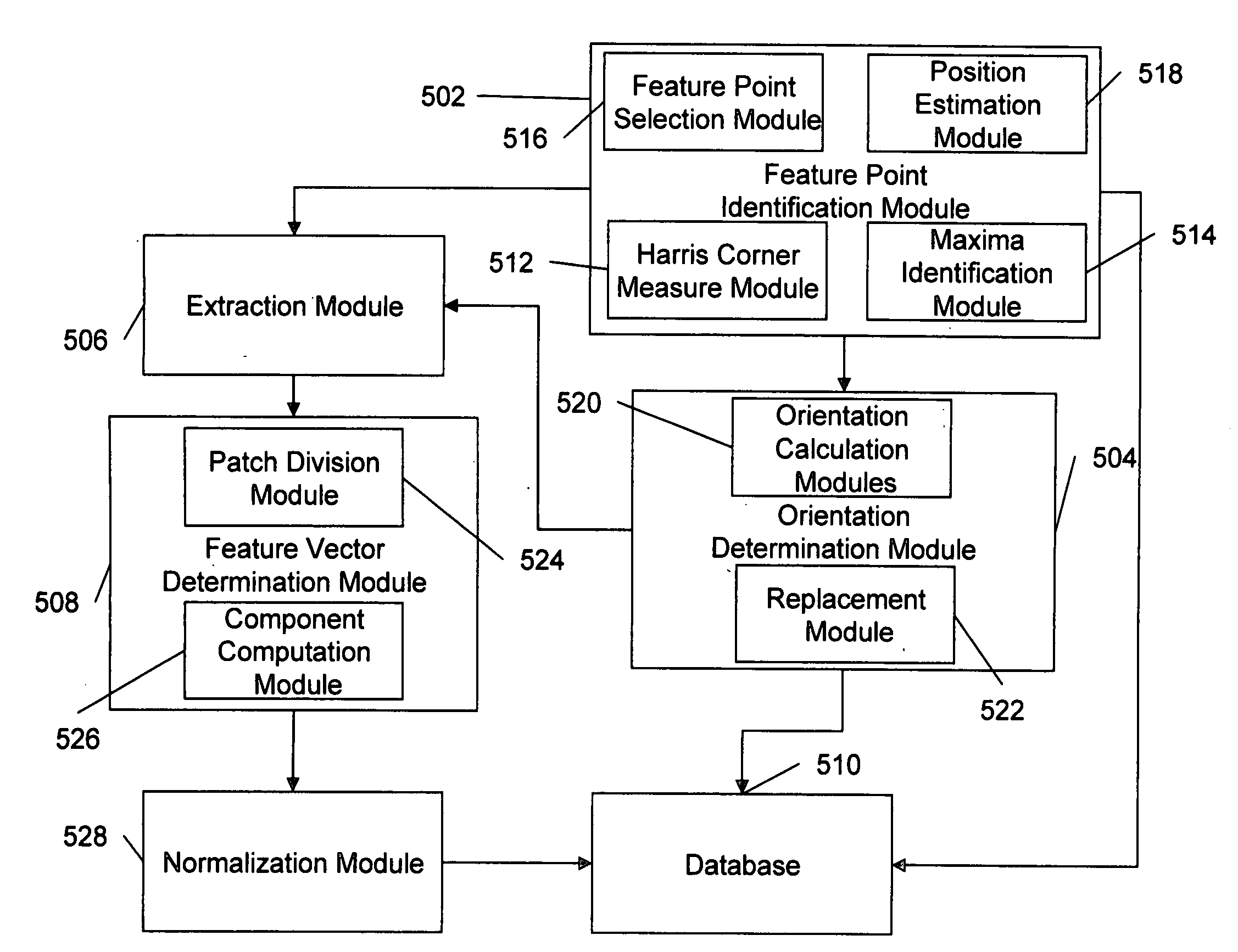
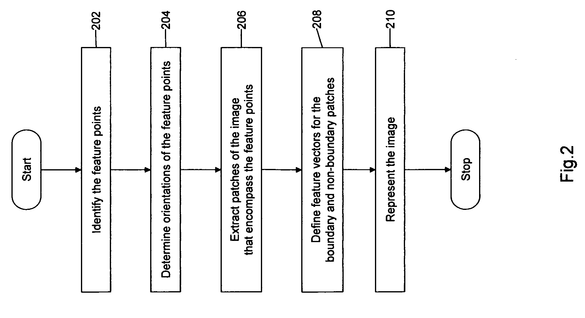
[0020]Various embodiments of the present invention relate to a method, system and computer program product for representing an image. The method uses the feature points present in the image to describe the image. Therefore, the first step in the method is to determine the feature points in the image. Thereafter, the orientation of the feature points is determined by combining the orientations obtained from a set of orientation calculating algorithms. Thereafter, a patch is extracted around the feature points and a feature vector is defined for the extracted patches. The feature vector is normalized in such a way that no component of the feature vector is greater than a specified threshold.

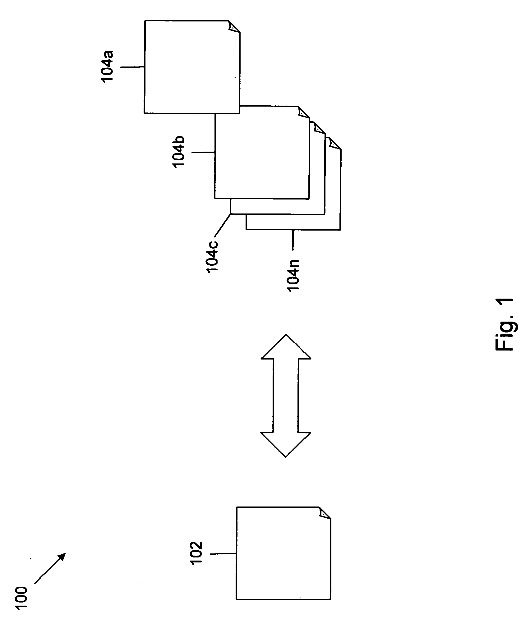
[0021]FIG. 1 illustrates an environment 100, where various embodiments of the present invention can be practiced. The present invention may be used in the field of computer vision, object recognition, motion tracking and 3D modeling. The images may be of different formats such as JPEG, GIF, BMP, an...


PUM


Abstract

A method, system and computer program product for representing an image is provided. The image that needs to be represented is represented in the form of a Gaussian pyramid which is a scale-space representation of the image and includes several pyramid images. The feature points in the pyramid images are identified and a specified number of feature points are selected. The orientations of the selected feature points are obtained by using a set of orientation calculating algorithms. A patch is extracted around the feature point in the pyramid images based on the orientations of the feature point and the sampling factor of the pyramid image. The boundary patches in lo the pyramid images are extracted by padding the pyramid images with extra pixels. The feature vectors of the extracted patches are defined. These feature vectors are normalized so that the components in the feature vectors are less than a threshold.

Description

BACKGROUND OF THE INVENTION[0001]The invention relates generally to the field of digital image processing. More specifically, the invention relates to a method and system for representing the content of an image so that it can be matched with another image containing the same content.[0002]Image matching is a fundamental technique that is being used in computer vision, object recognition, motion tracking, 3D modeling, and the like. Image matching is performed to check whether two images have the same content. The two images that need to be compared may not be exactly the same. For example, one image may be rotated or taken from a different viewpoint as compared to the other image, or it may be a zoomed version of the other image. Further, the two images may be taken under different lighting conditions. Despite such variations in the two images, they contain the same content, scene or object. Therefore, image matching techniques are used to match images effectively.[0003]Typical imag...

Claims


Application Information

Patent Timeline
IPC IPC(8): G06K9/46
CPCG06K9/4609G06T9/00G06K9/6212G06K9/4671G06V10/443G06V10/462G06V10/758G06F18/213
Inventor RUZON, MARK A.MANMATHA, RAGHAVANTANGUAY, DONALD
Owner A9 COM INC
Why Eureka
Try Eureka