
Modifying commands

a technology of command and command, applied in the field of modifying commands, can solve the problems of electro-mechanical delay, latency, and other electro-mechanical delays associated with meliorate seek tim

Active Publication Date: 2010-07-15
MICRON TECH INC
View PDF10 Cites 150 Cited by
  • Summary
  • Abstract
  • Description
  • Claims
  • Application Information

AI Technical Summary

Problems solved by technology

For example, SSDs may have superior performance when compared to magnetic disk drives due to their lack of moving parts, which may ameliorate seek time, latency, and other electro-mechanical delays associated with magnetic disk drives.

Method used


Image

  • Modifying commands
  • Modifying commands
  • Modifying commands

Examples


Embodiment Construction

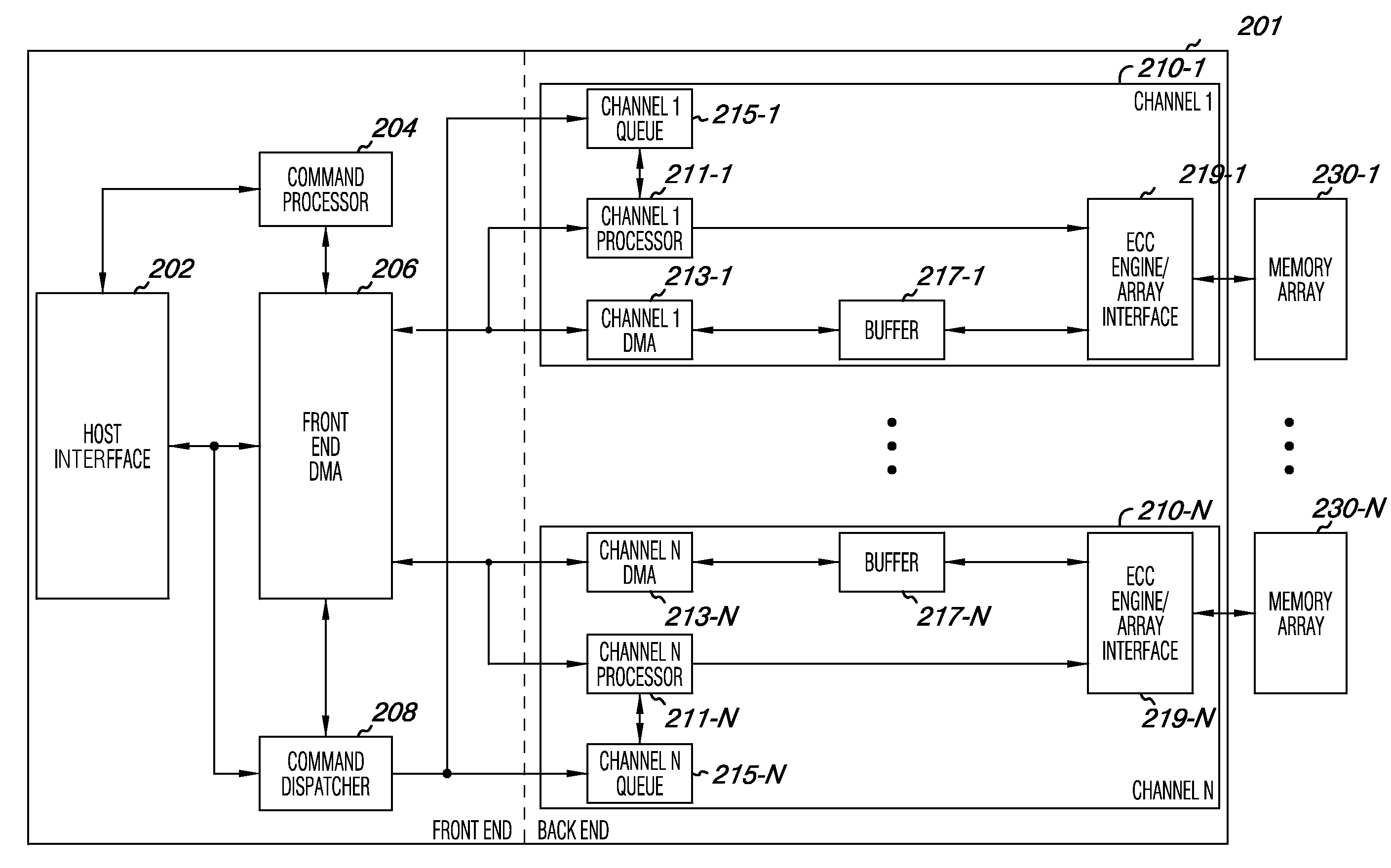
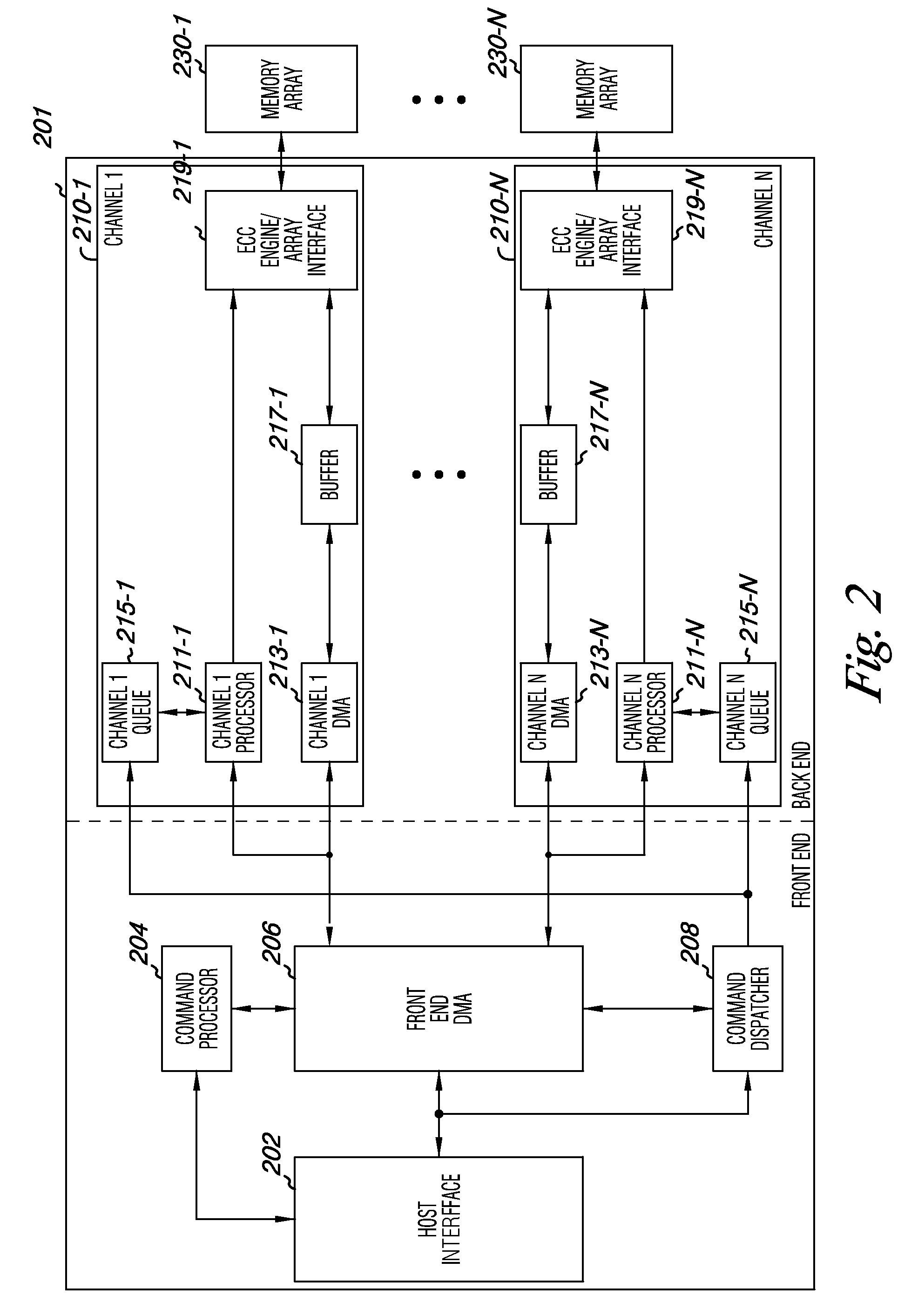
[0011]The present disclosure includes methods, devices, modules, and systems for modifying commands. One device embodiment includes a memory controller including a channel, wherein the channel includes a command queue configured to hold commands, and circuitry configured to modify at least a number of commands in the queue and execute the modified commands.

[0012]In the following detailed description of the present disclosure, reference is made to the accompanying drawings that form a part hereof, and in which is shown by way of illustration how one or more embodiments of the disclosure may be practiced. These embodiments are described in sufficient detail to enable those of ordinary skill in the art to practice the embodiments of this disclosure, and it is to be understood that other embodiments may be utilized and that process, electrical, and / or structural changes may be made without departing from the scope of the present disclosure. As used herein, the designators “N” and “M”, p...


PUM


Abstract

The present disclosure includes methods, devices, modules, and systems for modifying commands. One device embodiment includes a memory controller including a channel, wherein the channel includes a command queue configured to hold commands, and circuitry configured to modify at least a number of commands in the queue and execute the modified commands.

Description

TECHNICAL FIELD [0001]The present disclosure relates generally to semiconductor memory devices, methods, and systems, and more particularly, to modifying commands.BACKGROUND [0002]Memory devices are typically provided as internal, semiconductor, integrated circuits in computers or other electronic devices. There are many different types of memory, including volatile and non-volatile memory. Volatile memory can require power to maintain its data and can include random-access memory (RAM), dynamic random access memory (DRAM), and synchronous dynamic random access memory (SDRAM), among others. Non-volatile memory can provide persistent data by retaining stored information when not powered and can include NAND flash memory, NOR flash memory, read only memory (ROM), Electrically Erasable Programmable ROM (EEPROM), Erasable Programmable ROM (EPROM), and phase change random access memory (PCRAM), among others.[0003]Memory devices can be combined together to form a solid state drive (SSD). ...

Claims


Application Information

Patent Timeline
IPC IPC(8): G06F9/318
CPCG06F13/1642G06F13/1631G06F9/06G06F12/00G06F13/16
Inventor ASNAASHARI, MEHDI
Owner MICRON TECH INC
Features
  • Generate Ideas
  • Intellectual Property
  • Life Sciences
  • Materials
  • Tech Scout
  • Unparalleled Data Quality
  • Higher Quality Content
  • 60% Fewer Hallucinations
Learn More