Roof flashing

a technology for roofs and flashings, applied in the field of roof flashings, can solve the problems of too much angle for the roof membrane to handle, asphalt membranes still have a tendency to crack and split at the 45-degree angle, absorb water and decompose, etc., and achieve the effect of preventing moisture from destroying

Inactive Publication Date: 2010-07-22
PERROT JR JOHN J
View PDF36 Cites 12 Cited by
  • Summary
  • Abstract
  • Description
  • Claims
  • Application Information

AI Technical Summary

Benefits of technology

[0007]It is, therefore, an object of the present invention to provide a roof flashing assembly that can be used along the roof edge to prevent

Problems solved by technology

However, the triangular cross sectioned cant strips create a stressful angle for the membranes to follow as the transition from the horizontal roofing deck to the triangular cross sectioned cant strip still requires a transition angle of 45 degrees and this often is too much angle for the roofing membrane to handle over time.
In particular, asphalt membranes still have a tendency to crack and split at the 45-degree angle between the horizontal decking surface and the cant strip surface.
Second, as the cant strip is made of wood or wood fiber material, they can absorb water and decompose if small cracks in the membrane go undetected and water penetrates to the cant strip surface.
The cant strip can hold this moisture and subsequently promote dry rot of wood deck

Method used


Image

  • Roof flashing
  • Roof flashing
  • Roof flashing

Examples


first embodiment

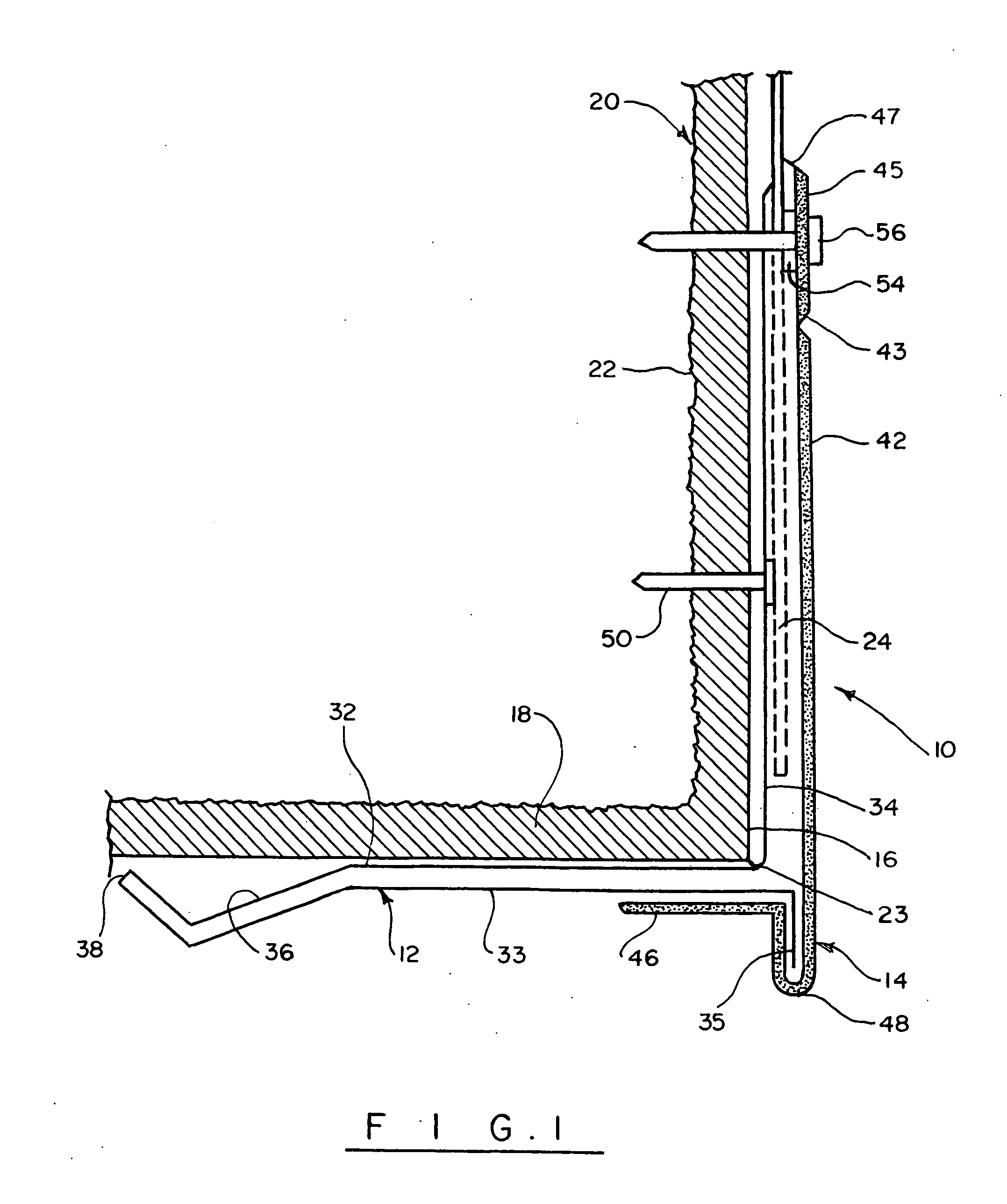
[0015]Turning now to the drawings in more detail, numeral 10 designates the edge flashing assembly according to the invention. The flashing assembly 10 comprises a first flashing member 12 and a second flashing member, or cap 14 adapted for installation at the top 16 of a vertical wall 18. The system 10 is secured to a building 20 having a number of side walls 18 and a roof substructure 22. The system 10 is designed to be secured to the building 20 at the intersection or joining of the walls 18 and the roof 22 in order to provide a more water- and air-tight attachment of a roofing material or membrane 24 along the peripheral edge of the building structure 20.

[0016]The first member 12 comprises an inner vertical part 32 and an outer vertical part 33, a locking flange 34 extending perpendicularly to the top of the inner vertical part 32, and a sealing flange 35, which extends perpendicularly to the outer vertical part 33 in a direction opposite to the locking flange 34. The lower ends...

second embodiment

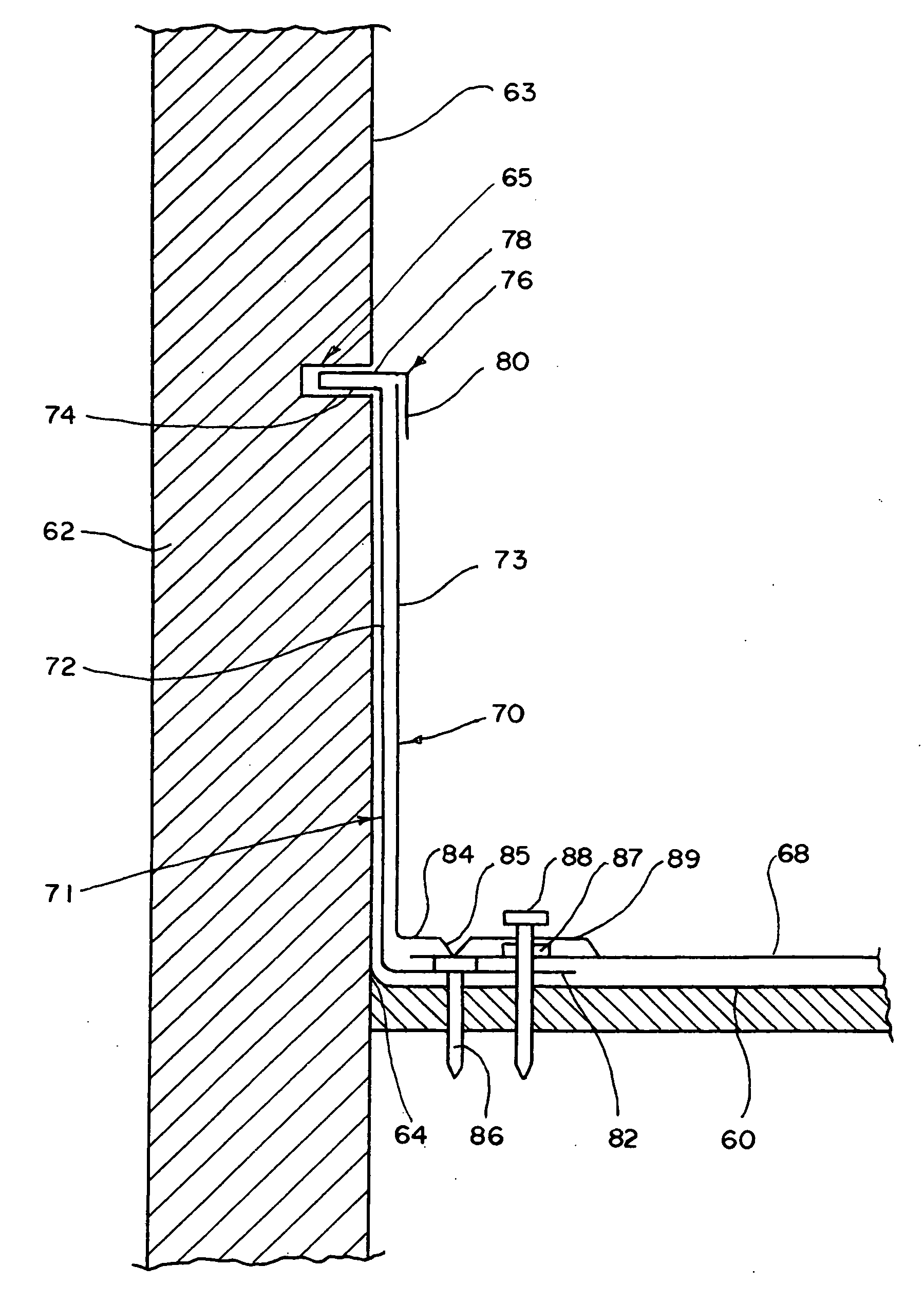
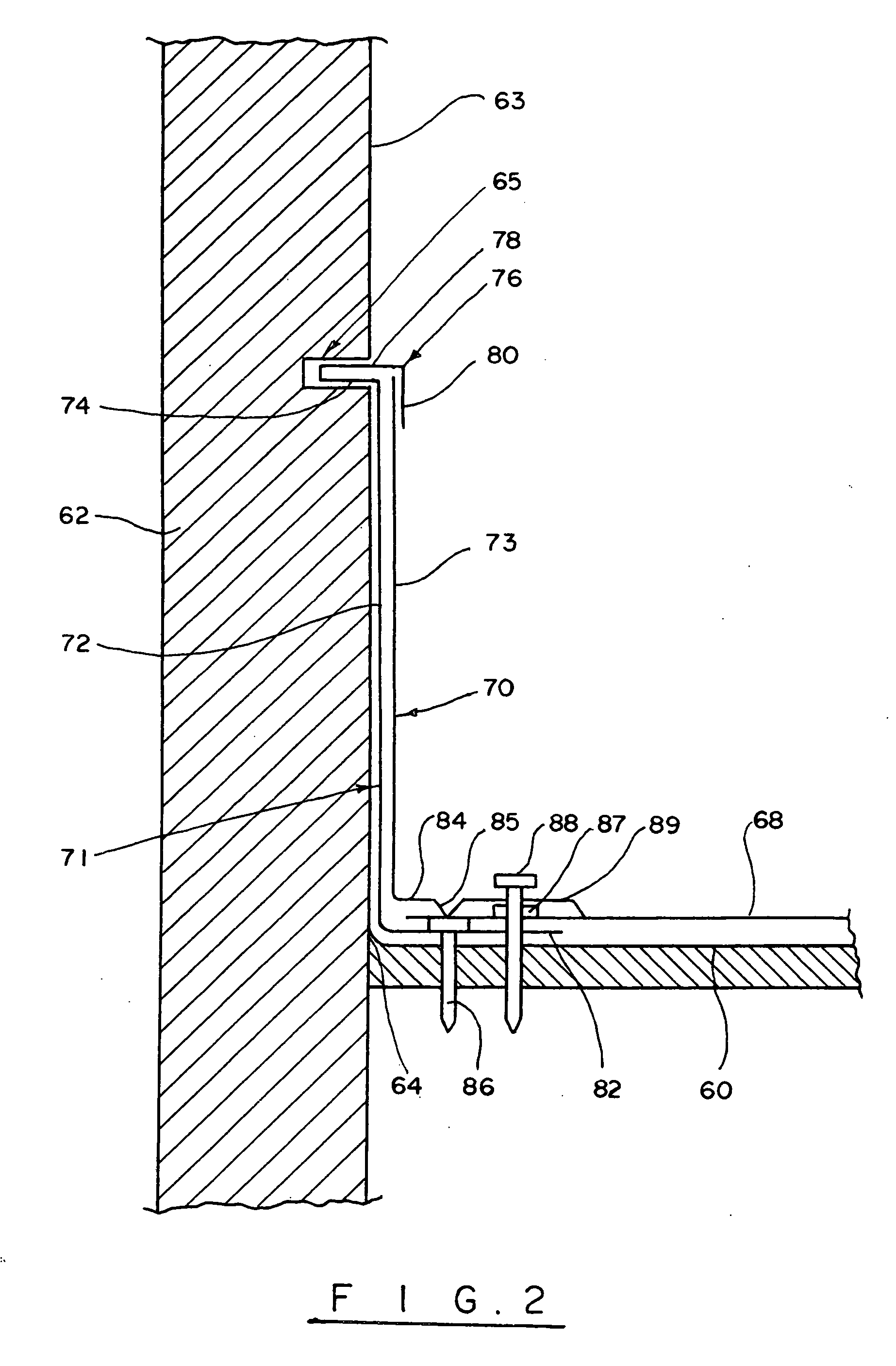
[0023]Turning now to this invention, reference will be made to FIG. 2, which illustrates a flashing assembly particularly adapted for use with parapet walls. As can be seen in the drawing, the roof substructure 60 joins a parapet wall 62 along a line 64. The roof substructure 60 can be made of plywood or other suitable material. A roofing membrane or roofing material 68 covers the roof substructure 60.

[0024]The parapet wall 62 usually extends at a right angle to the roof substructure 60. As discussed above, the conventional technique would be to place a cant strip along the line 64. However, a strong wind can rip off the roof, breaking the cant strip. The plywood roof substructure 60 then becomes exposed to the environment. The present invention contemplates reinforcement of the weak point—the 90-degree connection between the roof and the parapet wall. According to the present invention, a flashing assembly 70 is placed along the line 64 extending up the parapet wall surface 63 and ...


PUM


Abstract

A flashing assembly for reinforcing an interface defined between a roof and a portion of a building wall, either a flat roof or a flat roof with parapet wall. The flashing assembly has a first member configured for securing along the interface between the roof and the building wall and a second member for covering an upper part of the first member. The first member has an inner vertical part adapted for extending along the building wall, a locking flange extending at a right angle to the inner vertical part, and an outer vertical part extending in a substantially parallel orientation to the inner vertical part. In one aspect, the first member has an inclined bottom flange for diverting water away from the building while the top locking flange is secured to the roof. In another aspect, the flashing assembly has a top locking flange that is sealed in a groove formed in a parapet wall above the roof and a securing bottom flange, which is attached to the roof.

Description

BACKGROUND OF THE INVENTION[0001]This invention relates to the construction industry, and more particularly, to roof flashings of the type which reinforce the interface between a wall and a roof edge to provide a waterproof and weather resistant seal along the edge of the roof.[0002]Roof flashing is conventionally used to provide a waterproof and weather resistant seal about the periphery of the roof edge, as well as around the pipes and vent stacks. The flashing is usually made of sheet metal, flexible molded rubber or other synthetic material formed in an appropriate shape to seal the periphery of the projecting members, and is normally made to extend slightly above the level of the roof, to limit the infiltration of moisture into the building. In flat roofs, the roof edge is conventionally sealed using the so-called cant strips. Generally, roof systems used on most building structures, and particularly flat-roof buildings, require some type of blocking to provide a base for the a...

Claims


Application Information

Patent Timeline
IPC IPC(8): E04D1/36E04B1/00
CPCE04D13/155E04D13/1415
Inventor PERROT, JR., JOHN J.
Owner PERROT JR JOHN J
Why Eureka
Try Eureka