Piston engine comprising member to cover bottom face of valve head of poppet valve
Inactive Publication Date: 2010-07-22
YAOITA YASUHITO
View PDF5 Cites 3 Cited by
Summary
Abstract
Description
Claims
Application Information
AI Technical Summary
This helps you quickly interpret patents by identifying the three key elements:
Problems solved by technology
Method used
Benefits of technology
Benefits of technology
[0025]A second object is to lower a temperature of the valve when it is used as an exhaust valve.
[0058]Further, a total area of the intake and exhaust valves of the engine according to the three aspects of the present invention is larger than engines provided with overhead valves only in a main cylinder. Therefore, intake and exhaust resistance reduces especially when rotating at high speed. Output power of the engine of the invention thus can increase.
Problems solved by technology
As a result, the negative work increases.
This increases the loss caused by the suction resistance, so that the torque lowers.
As a result, just after the piston leaves the bottom dead point, the exhaust resistance causes a great loss.
Consequently, the combustion chamber having a suction valve facing the top of the piston and a side valve cannot have a high combustion ratio, so that the engine efficiency is low.
As a result, knocking occurs.
If the strokes of the piston are longer than its diameter, the combustion gas conversion efficiency is high, but the suction efficiency is low when the engine rotates at high speed.
The low suction efficiency leads to low torque.
If the piston strokes are shorter than the piston diameter, the suction efficiency is high when the engine rotates at high speed, but the combustion gas conversion efficiency is low.
Therefore, long strokes of the pistons of conventional spark ignition engines have been incompatible with torque increases that may be caused when the engines rotate at high speed.
Method used
Image
Click on the blue label to locate the original text in one second.
Reading with bidirectional positioning of images and text.
Examples
first embodiment
[0069]A first embodiment will be described.
[0070]The first embodiment is included in the first aspect.
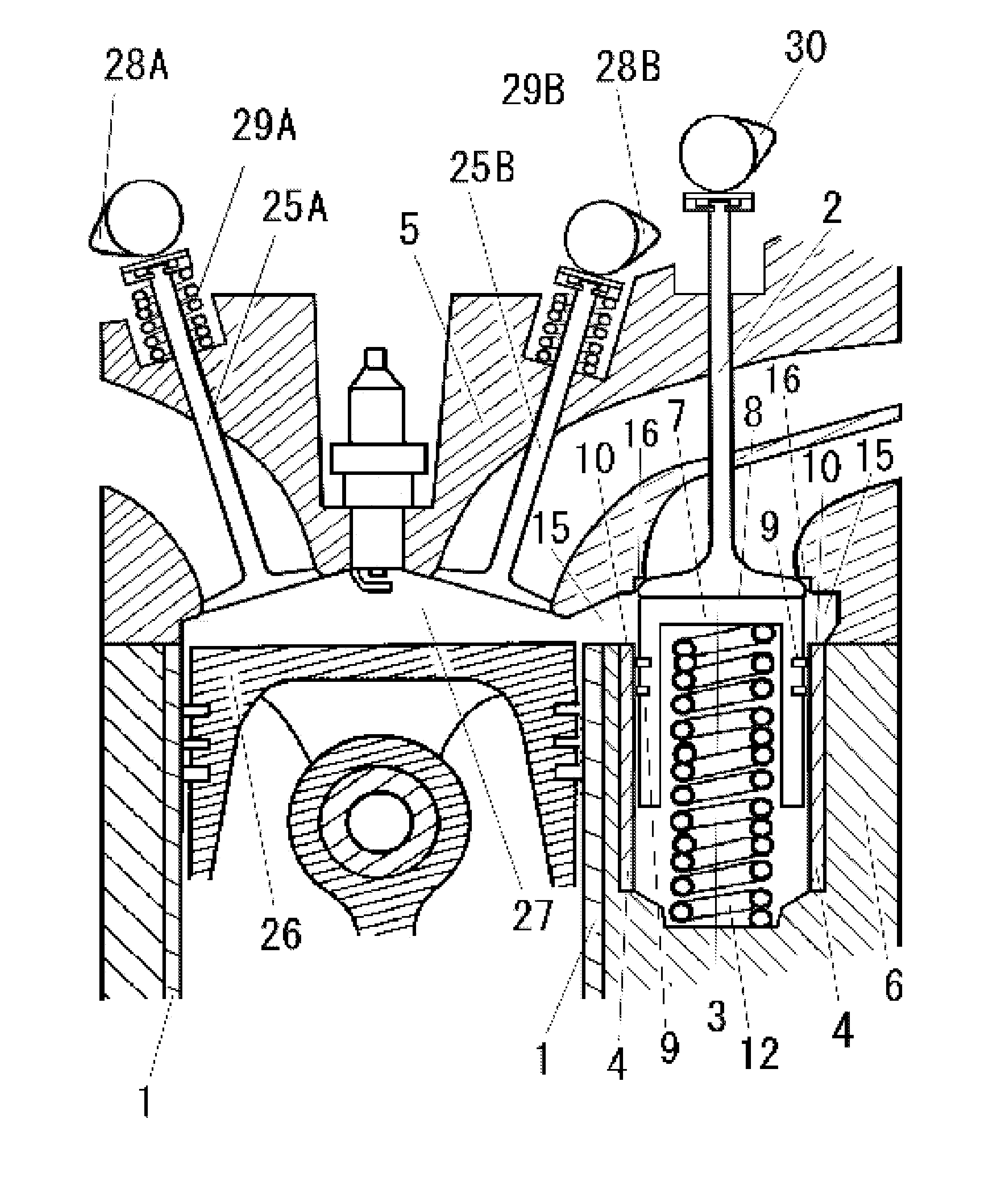
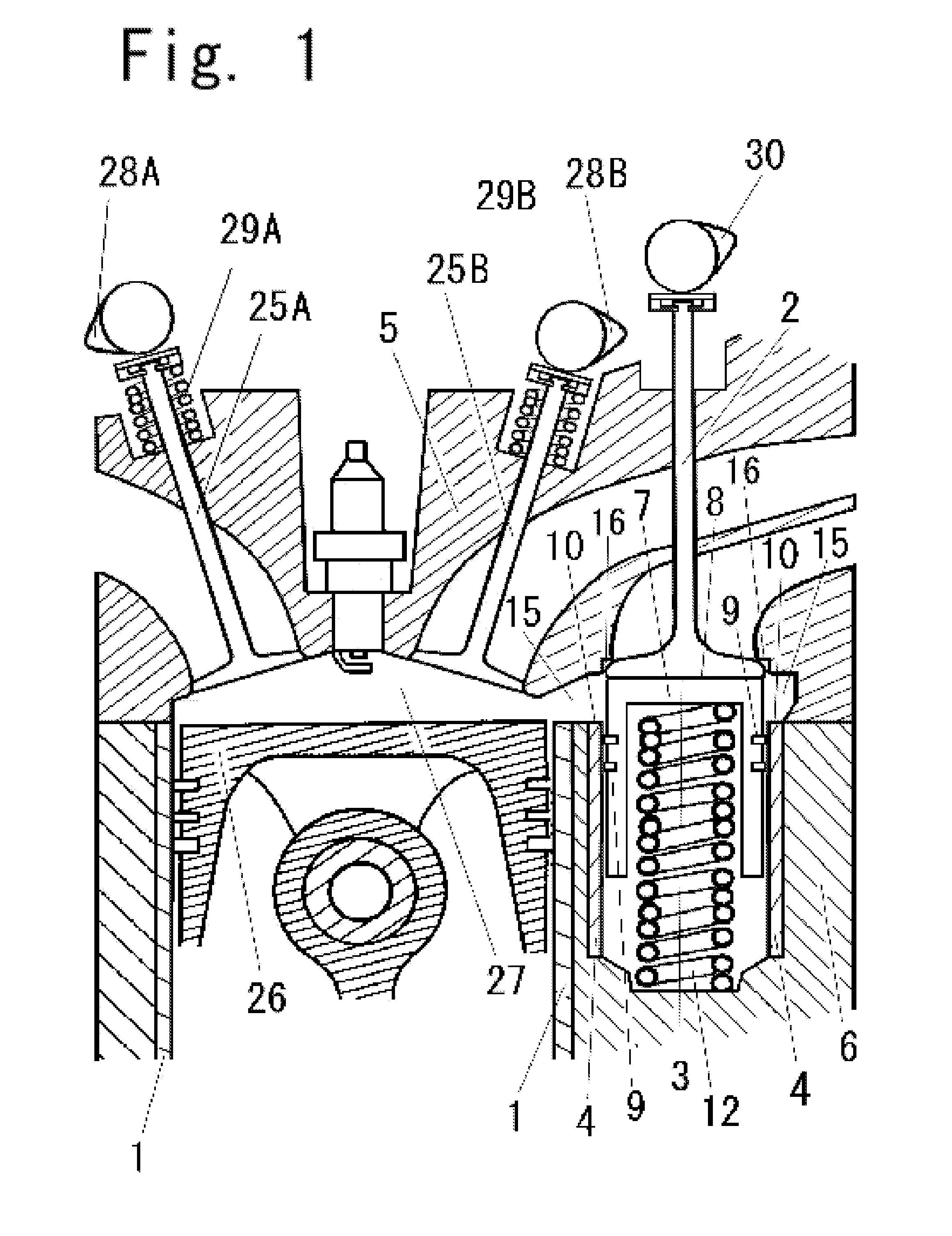
[0071]A piston engine shown in FIGS. 1 and 2 comprises a cylinder head 5, a cylinder block 6, a main cylinder 1, a piston 26, a sub cylinder 4, overhead valves 25A and 25B, and a poppet valve 2.
[0072]The piston 26 reciprocates in the main cylinder 1. A combustion chamber 27 is defined between the cylinder head 5 and the piston 26. The combustion chamber 27 further extends outside the main cylinder 1. An inner wall of the combustion chamber 27 comprises a first part and a second part. The first part represents the inner wall which faces with an upper face of the piston 26. The second part represents the inner wall of the extended part outside the main cylinder 1.
[0073]The combustion chamber 27 may extend both right and left sides outside the main cylinder 1.
[0074]The sub cylinder 4 is installed in the cylinder block 6 which locates outside the main cylinder 1.
[0126]In FIG. 4, the sub cylinder 4 is provided in the cylinder head 5. In this case, the gas path contacting with the poppet valve 2 is provided in the cylinder block. The poppet valve 2 provided outside the cylinder is a side valve.
third embodiment
[0127]The third embodiment will be described.
[0128]In FIG. 5, a pneumatic unit, hydraulic unit 19, electromagnetic unit or electric unit is employed in place of the spring 12. These units bias the valve cover 7 so that the upper face 8 presses the bottom face of the poppet valve 2. These units and the third spring 12 are to bias the valve cover 7 toward the valve sheet 16.
[0129]In FIG. 5, the compression ring 9 is subject to the pressure of the combustion gas so that the valve cover is pushed downwards. The valve cover and the bottom face of the poppet valve are not separated from each other by the pressing force.
[0130]The above-described units including the hydraulic unit 19 bias the valve cover toward the valve sheet 16 of the poppet valve 2 with a force not less than this pressing force.
PUM
Abstract
To achieve high compression ratio and lower temperature of the exhaust poppet valve in an engine provided with a poppet valve on an extend part of a combustion chamber outside a main cylinder, disclosed is a valve cover having a cylindrical side face and upper face, an compression ring either the cylindrical side face and an inner wall of the sub cylinder, means to contact closely a bottom face of a poppet valve and the upper face of the valve cover, the upper part of the valve cover occupying most part of the combustion chamber facing with the bottom face, the valve cover moves along with the poppet valve when the poppet valve is lifted, a combination of overhead valves and the poppet valve including one intake valve and one exhaust valve, and total number of the overhead valve and poppet valve is not less than 3.
Description
BACKGROUND OF THE INVENTION[0001]1. Field of the Invention[0002]The present invention relates to a piston engine comprising a member to cover a bottom face of a valve head of a poppet valve. When the combustion chamber extends outside the main cylinder, the member occupies a space facing with the bottom face of the poppet valve provided outside a main cylinder in a combustion chamber.[0003]2. Description of the Related Art[0004]The suction resistance and exhaust resistance of a four cycle engine are high when it rotates at high speed. The suction lifts in this engine are extremely small in the initial stages of the periods when the suction valve is open. The initial stages are shorter when the engine rotates at a higher speed. This restricts the inflow of suction gas. As a result, in the initial stages of the periods when the suction valve is open, the pressure in the cylinder is lower than the pressure at the back of the piston.[0005]Under this condition, the piston keeps moving do...
Claims
Application Information
Patent Timeline
Application Date:The date an application was filed.
Publication Date:The date a patent or application was officially published.
First Publication Date:The earliest publication date of a patent with the same application number.
Issue Date:Publication date of the patent grant document.
PCT Entry Date:The Entry date of PCT National Phase.
Estimated Expiry Date:The statutory expiry date of a patent right according to the Patent Law, and it is the longest term of protection that the patent right can achieve without the termination of the patent right due to other reasons(Term extension factor has been taken into account ).
Invalid Date:Actual expiry date is based on effective date or publication date of legal transaction data of invalid patent.

